Flowing fluid conditioner

a technology of flowing fluid and temperature conditioning, which is applied in the direction of instruments, machines/engines, heat measurement, etc., can solve the problems of large volume exchangers with correspondingly large pressure drop, small temperature gain, and unsuitable mobile devices such as vehicles, so as to reduce fuel consumption, maintain the performance of larger engines, and reduce emissions

Inactive Publication Date: 2005-04-21
PERKINS MICHAEL T
View PDF22 Cites 60 Cited by
  • Summary
  • Abstract
  • Description
  • Claims
  • Application Information

AI Technical Summary

Benefits of technology

[0028] o. It is another object of FFC to be embeddable such that it can be built right into devices such as existing intake or outlet pipes.
[0029] In accordance with the present invention, the Flowing Fluid Conditioner (FFC) discloses a system that can assist in the implementation of smaller engines with reduced fuel consumption, lowered emissions while maintaining performance of larger engines these more efficient versions will replace. FFC affords a simple, flexible, reliable intake flowing fluid chiller / warmer system that will raise or lower intake fluid temperature as required, or when on demand by the device and system. The present invention is specifically a flowing fluid conditioner system, which consists of an active thermoelectric device, a collection of sensors, a thermal exchanger / reservoir, fluid control valves, a by-pass pathway, and a controllable fluid pathway. An external controller can regulate relative amounts of electric current to the active cooling device and control the valves to divert the path of airflow through the multi-chamber (consisting of by-pass and controllable fluid chambers) intercooler. Thermoelectric devices specifically Peltier junctions or Thermotunneling diodes are known for their ability to heat or cool by selection of power polarity to these devices.
[0030] Under differing engine conditions such as under low engine load or high engine load, the flowing fluid conditioner system can respond to signals from an external controller in order to optimize engine operation efficiency and preserve battery charge. Typically, a vehicle with FFC starting in a cold environment would pre-warm exchanger / reservoir prior to start. When started (FFC will shut down during cold cranking to minimize starting load) FFC will continue to warm incoming air for initial performance and emissions reductions. In contrast (changed conditions) a vehicle with FFC in a warm environment will “charge” exchanger / reservoir cold before or after starting. This exchanger / reservoir state of cold will be kept cold in the insulated housing with a trickle current until a demand condition accesses exchanger / reservoir for temperature conditioning and additional available performance.
[0031] The FFC responds to signals from the controller to supply current to the thermoelectric cooler that cause it to heat or cool exchanger / reservoir. Command signals from controller also cause the FFC to directly adjust the valve or valves to increase airflow through the bypass chamber or divert airflow over the exchanger / reservoir chamber to the engine.
[0032] As a result of the temperature of engine aspiration being lowered on-demand, the engine wide-open throttle power is increased and because a smaller displacement engine is able to produce more power overall fuel efficiency can be increased. In the event that the external controller signal fails, the failure position of the FFC valve is in the normal aspiration position. The majority of performance requirements when driving on streets and highways are satisfied by short bursts of power on the order of less than thirty seconds. Even drag races between performance vehicles are typically staged for a quarter mile and completed in less than thirty seconds. The FFC invention is ideally suited to be adapted to hybrid and combination designs of superchargers and turbochargers, but also with normally aspirated engine configurations. The FFC invention can be used as an input to any system that can benefit from the conditioning of hot or cold fluids.
[0033] The air conditioned by the FFC invention can be further used as an input to any system that can benefit from cooling hot air to make it denser as in a combustion engine to increase power or to warm very cold air for improved starting. The FFC invention will also function as an on-demand in line intercooler. The present invention can work with existing air-to-air, water-to-water, or air-to-water intercoolers. The FFC invention has a small footprint, which can be built into housings, castings or adapters for very localized fluid temperature conditioning. The present invention can also be configured to condition the temperature of coolant in air-to-water or coolant intercoolers that are used during on-demand situations.

Problems solved by technology

These systems suffer from bulkiness, need to be recharged (as misters and fluid injectors) and fragile support equipment as with compressors, and are therefore unsuitable for mobile devices such as vehicles.
Similar problems occur with large volume exchangers having correspondingly large pressure drops and small temperature gains as in air-to-air intercoolers.
Likewise, requirements for reservoirs and ice baths as with ice chillers make their use in vehicles inconvenient were vehicles are intended to be mobile.
Liquid misters and injectors require frequent replenishment and sophisticated controls and nozzles, and reliability problems are often experienced.
A mister cooled turbo system set up for maximum output would cause a host engine to self-destruct if fluid was low or delivery portion became “clogged” in the mister system.
Temperature directly affects the performance of an internal combustion engine when under heavy loads.
Air charge temperature also affects wear and reliability of engine components when under heavy loads.
However, said designs such as Iaculio's U.S. Pat. No. 5,547,019, August 1996 would not facilitate the desired results.
The preferred embodiments described by Iacullo require too much cooling from the thermoelectric devices, resulting in the need for immediate response by the active devices.
This is not possible without massive peltier junctions and thousands of amps current applied to the intercooler.
Producing the amount of heat removal required to chill the charged air to the necessary temperature, would consume excessive power and result in a continuous parasitic drain on the battery.
The subsequent drag on engine power would yield a considerable net loss of performance.
Iaculio's system will also have too slow a response time to be effective with the type of loads, and under such conditions, that can be characterized as “on demand operation”.
The intercooler in Iacuilo's system does not give enough detail to demonstrate that it will have sufficient capacity to cool charged air.
An intercooler located directly in the air path for normal operation will not be capable of “storing” cold reserves for specific uses.
No parallel, by-pass or alternative air passage is envisioned to allow normal operation of the system that will not deplete a reserve in an exchanger.
Chilling incoming air during conditions other than wide-open-throttle (WOT) or heavy load, does not improve engine efficiency and will result in a net power loss when compared to an engine system without chilling.
Iacuilo's system offers no substance to counteract the above deficits and as disclosed does not appear to be of sufficient capacity to cool the charged air.
Iacuilo also does not provide for practical control for embodiment operation.
And without strategic, adequate controls, requiring operation of the Peltier Junctions in a steady-state condition during vehicle driving is not practical.
Furthermore, the heat sinks surfaces proposed by Iacuilo do not appear sufficient to afford adequate heat dissipation.
Also, no isolation for heat or moisture is provided around the heat pump hot or cold plates thereby reducing efficiency, capacity, and heat pump life.
This may be allowable for certain aftermarket applications, however, a lack of sensors and actuators for an automated controller that monitors engine as well as add-on chiller will restrict benefits and applications of said systems.
Without a WOT signal available to a robust controller said system will continue to draw large amounts of current during high demand operation (when system is intend to supplement performance) compromising performance.
However, extensive modifications of vehicle ducting, controls, vents, plumbing and engine compartment are required.
These requirements make such systems more expensive, more time consuming to install, and more complicated to retrofit for existing vehicles.
This makes air conditioner based intercoolers impractical for these applications.
While such an approach could be physically implemented, the resulting embodiment, as described by Pelkey, would suffer from the above-mentioned shortcomings, and also have an overall loss of power in real applications.
That is, there is no advantage to conditioning during normal driving because such cooling needs would be prohibitively power demanding.
Also, cooling response time (without a reservoir of stored BTUs) is essentially non-responsive.
Therefore an inline cooling solution is compromised both in the ability to perform under demand conditions as required in normal driving conditions for passing, and for competition in drag racing type events.
While certain advantages may seem available with these configurations connecting the input of an internal combustion engine compromises the occupants air and sound quality especially if a “back fire” should occur, risking fire and contamination.
While this may have some advantages the complexity and additional plumbing under the hood will produce little gain.
Without active elements and robust controllers added to this system full temperature operation will not be possible.
This includes very cold weather where warming is necessary and very hot situations where sub ambient conditioning of inlet air is required.
While hot and cold fluids can be separated by use of such tubes with compressed air (and to some extent vacuum as described by Lindberg) the overall efficiency of this type of system will be low.
The resulting performance of such a system will experience sufficient losses to mitigate any real power gains.
Despite technological advances with intercoolers, several critical weaknesses remain in all prior systems.
Prior art does not provide for large temperature gains in the charged air being by virtue of being air-to-air based intercoolers.
Of the active systems, prior art runs the thermoelectric to drain engine power and does not have a control mechanism to achieve efficiency of operation.
Also equipment for heat sink of prior art designs do not provide for stationary operation or moisture build up around the cold plates.
Prior art which makes use of air-to-water or which make dual use of the air conditioning system suffer from difficulty of installation and their monopolization of precious under hood real estate.

Method used


Image

  • Flowing fluid conditioner
  • Flowing fluid conditioner
  • Flowing fluid conditioner

Examples


embodiment 145

[0063]FIG. 3c is yet another alternative embodiment where direct fans are not usable (i.e. hazardous environment). A water-cooled heat exchanger embodiment 145 is employed. Exchanger 145 is comprised of water block 143, such as MCW5000T from Swiftech, power is carried over cable 110 from power source 112, gasket 139, and radiator 151 is shown. Hoses 147 such as ClearFlex 60 from Cool Technica (http: / / ww.cooltechnica.com ) connect block 143 to output of liquid pump 149 such as FloJet from PPL Motor Homes (http: / / ww.pplmotorhomes.com / parts / rv-pumps-water-filters-fixtures-1.htm#Water%20Pumps%20-%20Flojet) and radiator 151 such as Black Ice Micro from CoolTechnica Radiator 151 has fan 153 such as EC1202M12CA from Evercool (http: / / www.evercool.com) for thermal exchange. Additional hose 147 connects radiator 151 to reservoir 155. Reservoir 155 filled with water or suitable coolant has additional hose 147 connecting to input of pump 149. This embodiment allows efficient cooling and remote ...

embodiment 157

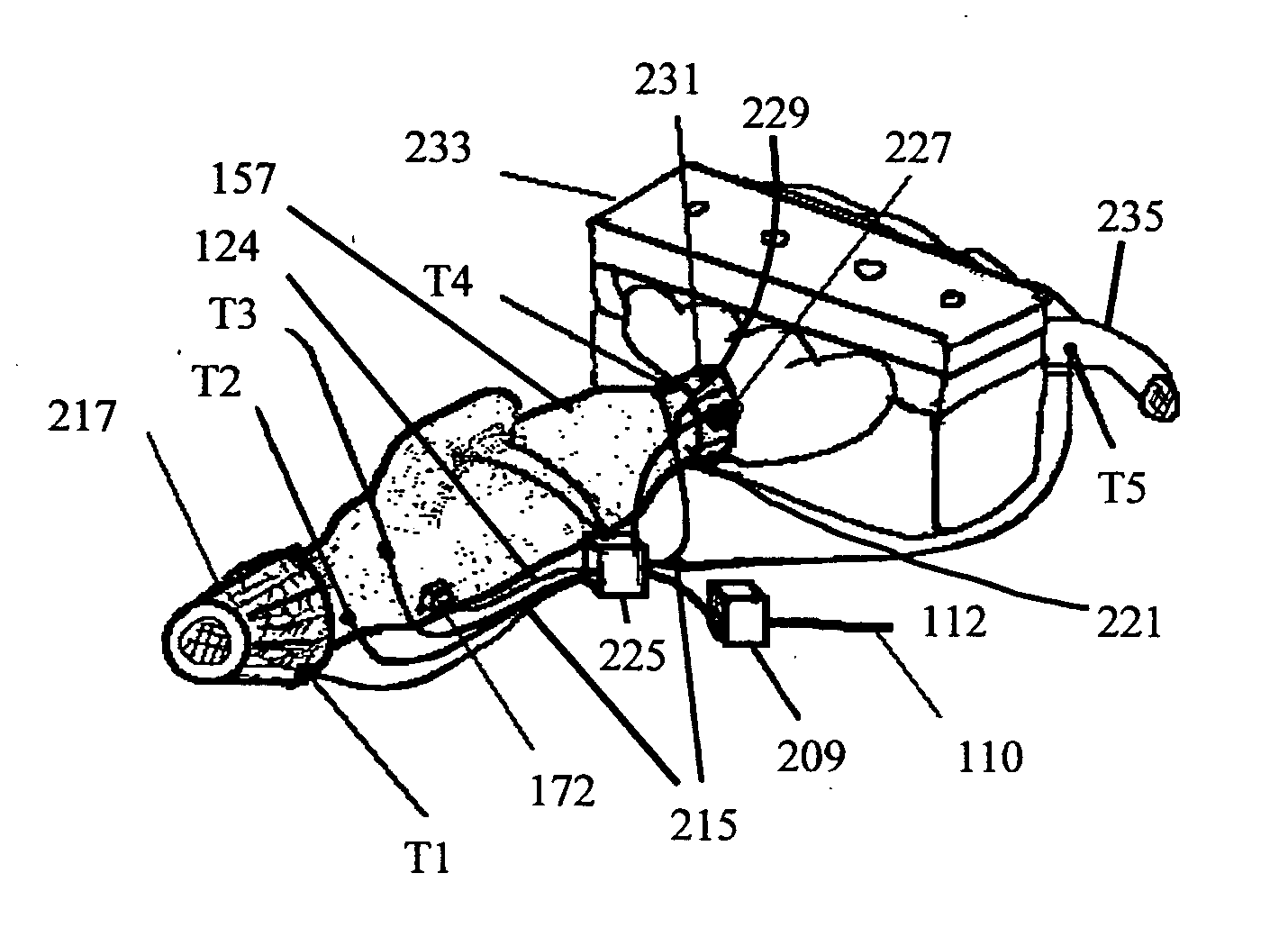
[0073]FIG. 7 shows a block diagram of my invention 157. Power is supplied to CPU 209 and controller 225 by cable 110 from supply 112. Thermistors (or thermocouples) T1, T2, T3, T4 and T5 for sensing working temperatures of this embodiment are connected over cable 215. Air cleaner 217 filters incoming air for protection of system components and engine parts. Incoming air temperature is monitored at T1. Actuator 172 selects direction of incoming air flows by controller 225 with signals from CPU 209. Temperature of air coming into conditioner 101 is monitored at T2. Incoming air to be chilled (or warmed) is directed through conditioner 101 and further directed through combiner 221 into throttle body 231. Temperature of conditioner 101 core is monitored at T3. Normal airflow is directed by actuator 172 through by pass 219 to combiner 221 into throttle body 231. Actuator 172 signaling from controller 225 / CPU 209, control and monitoring is accomplished over cable 170. Temperature of throt...


PUM

PropertyMeasurementUnit
temperatureaaaaaaaaaa
currentaaaaaaaaaa
voltageaaaaaaaaaa

Abstract

A method and system for temperature conditioning of engine intake air by use of controllable intercooler which consists of an active thermoelectric device and a controllable valve system which optimally directs the path of airflow through a plurality of chambers in response to signals from a controller in order to optimally provide temperature conditioned air to the engine. System features temperature storage isolated from heat soaked engine components allowing immediate and efficient conditioning of airflow into an internal combustion engine. Intelligent control of this device removes parasitic power drains during high demand situations.

Description

FEDERALLY SPONSORED RESEARCH [0001] Not Applicable SEQUENCE LISTING OR PROGRAM [0002] Not Applicable BACKGROUND [0003] 1. Field of the Invention [0004] This invention relates to systems for temperature conditioning of flowing fluids by using active conditioning devices. Specifically for cooling or heating of flowing fluids in applications that require efficiency in size, reliability, weight, flexibility and on-demand capability. [0005] 2. Description of Prior Art [0006] Existing devices for conditioning of fluids have relied on refrigeration with compressors, air-to-air intercoolers, liquid-to-air, fluid misting of intercoolers, fluid injection or ice bath chillers. These systems suffer from bulkiness, need to be recharged (as misters and fluid injectors) and fragile support equipment as with compressors, and are therefore unsuitable for mobile devices such as vehicles. Similar problems occur with large volume exchangers having correspondingly large pressure drops and small temperat...

Claims


Application Information

Patent Timeline
Patent Type & Authority Applications(United States)
IPC IPC(8): G01K13/02
CPCF02B29/0418F02B29/0481F02B29/0493Y02T10/166G01K2205/00Y02T10/146G01K13/02Y02T10/12
Inventor PERKINS, MICHAEL T.
Owner PERKINS MICHAEL T
Why Eureka
Try Eureka