Supercharge Your Innovation With Domain-Expert AI Agents!

Damping pressure reducing valve

A technology of a pressure reducing valve and a pressure reducing valve core, which is applied in the field of vibration reduction and pressure reducing valves

Active Publication Date: 2011-07-20
BEIJING TIANMA INTELLIGENT CONTROL TECH CO LTD
View PDF5 Cites 2 Cited by
  • Summary
  • Abstract
  • Description
  • Claims
  • Application Information

AI Technical Summary

Problems solved by technology

Its output pressure is adjusted according to the needs of different users

Method used


Image

  • Damping pressure reducing valve
  • Damping pressure reducing valve
  • Damping pressure reducing valve

Examples


specific Embodiment 1

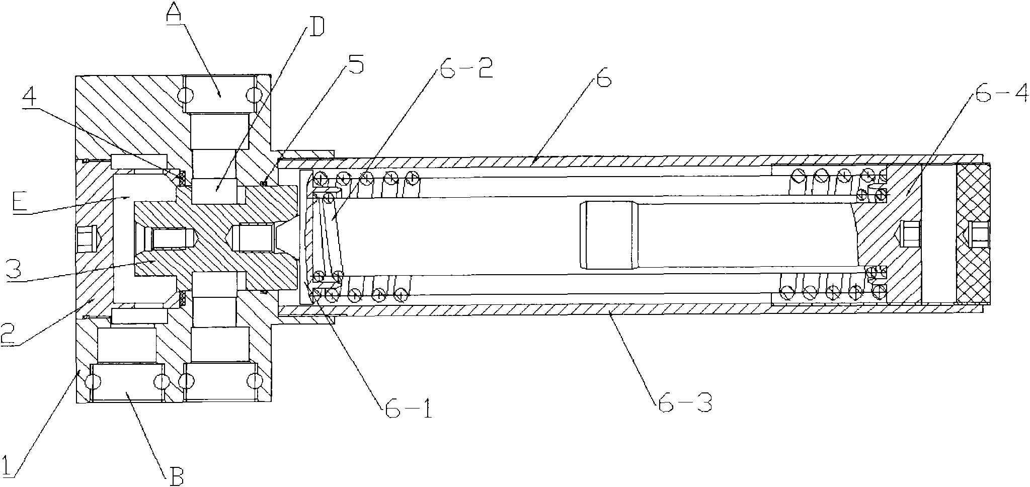
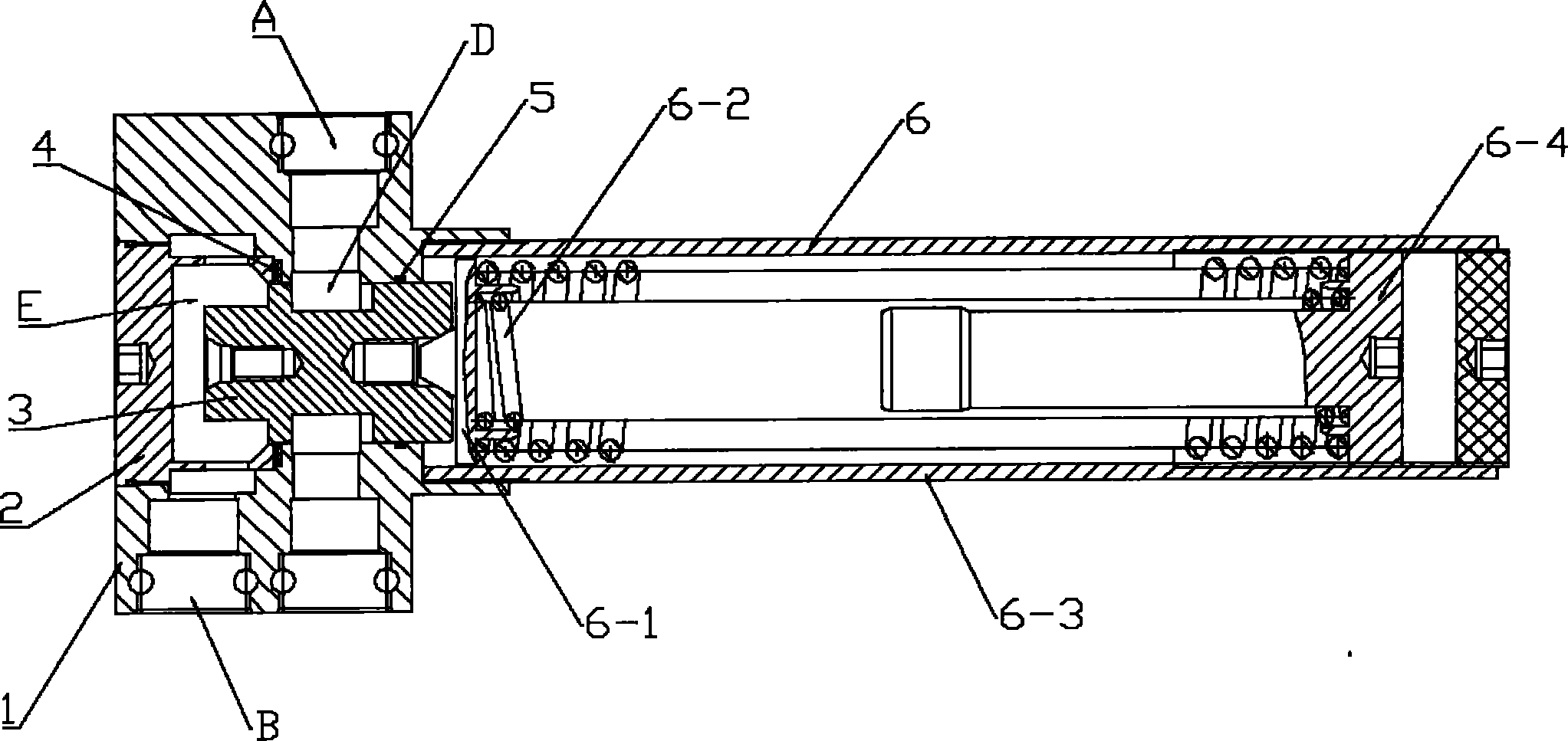
[0024] See attached figure 1 , which describes a preferred embodiment of the damping and pressure reducing valve according to the present invention. It includes a pressure reducing valve body, a pressure plug, a vibration reduction and pressure relief valve core, a pressure relief valve seat, a pressure relief sealing ring, and a pressure relief spring device. The pressure relief valve body has a pressure relief hole, and the vibration reduction and pressure relief valve core Installed in the decompression hole and can move along the axial direction of the decompression hole, an annular groove is arranged in the decompression hole, a decompression sealing ring is arranged in the annular groove, and the vibration reduction and decompression valve One end of the core has a cylindrical shaft section, the cylindrical shaft section cooperates with the pressure reducing valve body and the pressure reducing sealing ring to form a dynamic seal, and the cylindrical shaft section is con...

specific Embodiment 2

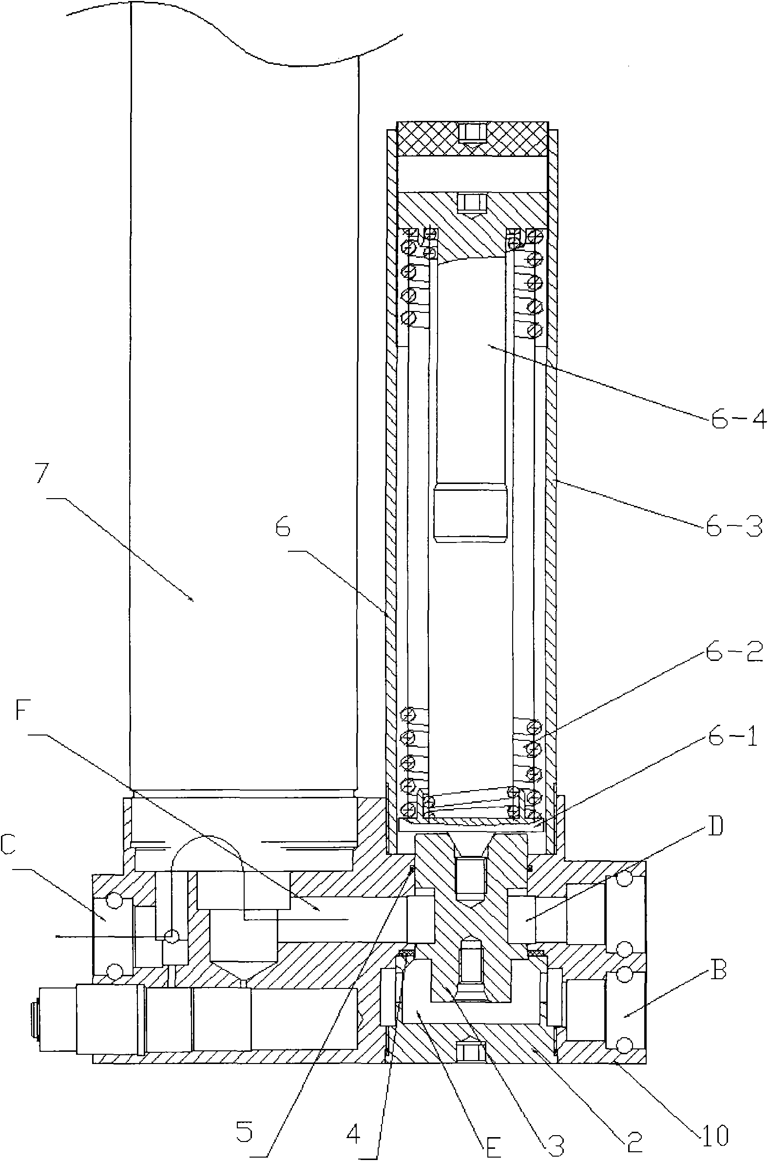
[0028] See attached figure 2 , which describes a preferred embodiment of the vibration damping and pressure reducing valve with filtering device according to the present invention. The basic structure of its decompression part is basically the same as that of the vibration-reducing pressure-reducing valve described in Embodiment 1, including the plugging of the vibration-reducing and reducing valve, the vibration-reducing and reducing valve core, the pressure-reducing valve seat, the pressure-reducing sealing ring, In addition to the decompression spring device, it also contains a vibration-reduction and pressure-relief valve body with a filter device and a filter device. The damping and pressure reducing valve body with filtering device has a pressure reducing hole, the vibration reducing and pressure reducing valve core is installed in the pressure reducing hole and can move along the axial direction of the pressure reducing hole, the pressure reducing valve core An annula...


PUM


Abstract

The invention discloses a damping pressure reducing valve, comprising a pressure reducing valve body, a pressure plug, a damping pressure reducing valve core, a pressure reducing valve seat, a pressure-reducing sealing ring and a pressuring-reducing spring device, wherein the pressure reducing valve body is provided with a pressure reducing hole, the damping pressure reducing valve core is arranged in the pressure reducing hole and can move along the axial direction of the pressure reducing hole, an annular slot is arranged in the pressure reducing hole and is internally provided with the pressure-reducing sealing ring, one end of the damping pressure reducing valve core is provided with a cylindrical shaft section which is matched with the pressure reducing valve body and the pressure-reducing sealing ring to form dynamic seal, and the cylindrical shaft section is connected with the pressure-reducing spring device for applying pressure to the cylindrical shaft section; the pressure reducing valve seat is arranged between the damping pressure reducing valve core and the pressure reducing valve body and is tightly pressed on the pressure reducing valve body through the pressure plug to form static seal between the pressure reducing valve seat and the pressure reducing valve body; and the other end of the damping pressure reducing core is provided with a cone frustum section with a conical face facing to the direction of the pressure reducing valve seat, a damping cylindrical shaft section is arranged on a part adjacent to one side of the conical face towards the pressure reducing valve seat, and a contact circle between the conical face of the damping pressure reducing valve core and the pressure reducing valve seat as well as the damping cylindrical shaft section adjacent to the conical face and an inner hole of the pressure reducing valve seat form a throttling damping pressure-reducing switch valve port.

Description

technical field [0001] The invention belongs to the technical field of hydraulic system control equipment, in particular to a damping and pressure reducing valve for coal mine water and emulsion medium. Background technique [0002] The prior art does not have a damping and pressure reducing valve suitable for coal mine water and emulsion medium. Coal mine hydraulic support uses emulsion as the working medium, and the emulsion pump station is set along the channel, and the working pressure currently used is 31.5 to 37.5MPa. Emulsion preparation needs stable pressure water, while the trough belt conveyor needs hydraulic tension, the scraper conveyor chain on the working face needs hydraulic tension, and its hydraulic coupler needs stable pressure water, coal shearer, scraper conveyor, reloader need Stable pressure water cooling, etc., but the pressure of the emulsion and water provided to them is higher than their needs, and the pressure fluctuates greatly. They need an outp...

Claims


Application Information

Patent Timeline
Patent Type & Authority Applications(China)
IPC IPC(8): F16K17/06F16K47/02F16K27/00B01D35/02
Inventor 李继周向虎罗跃勇
Owner BEIJING TIANMA INTELLIGENT CONTROL TECH CO LTD
Features
  • R&D
  • Intellectual Property
  • Life Sciences
  • Materials
  • Tech Scout
  • Unparalleled Data Quality
  • Higher Quality Content
  • 60% Fewer Hallucinations
Learn More