Azimuth angle adjustable mounting ring of square ceiling lamp

A technology of angle adjustment and installation ring, which is applied in the direction of lighting devices, lighting auxiliary devices, lighting device components, etc., can solve the problems of deviation in drilling, inconvenient installation orientation, and difficult installation orientation of square ceiling lamps, etc., to achieve time-saving effect

Inactive Publication Date: 2011-07-20
陶国胜
View PDF3 Cites 18 Cited by
  • Summary
  • Abstract
  • Description
  • Claims
  • Application Information

AI Technical Summary

Problems solved by technology

[0002] At present, the installation of the square ceiling lamp is to dismantle the lampshade first, hold the lamp to the ceiling, mark the screw holes on the ceiling lamp shell, use a percussion drill to drill the holes and place small wooden strips, and then lift the lamp to install the screws. Due to the deviation between the mark made on the ceiling and the drilling of the percussion drill on the prefabricated board, and the deviation between the placement of the small wooden strips and the installation of the screws, it is difficult to install the square ceiling light in a good position at one time. If the position is not good, it will affect the beauty of the ceiling light. Disassembly and re-drilling, installers sometimes have to install a lamp for one or two hours, and the orientation is not ideal. Many installers refuse to install square ceiling lamps on the grounds that it is inconvenient to install, and ask to replace them with round ceiling lamps.

Method used


Image

  • Azimuth angle adjustable mounting ring of square ceiling lamp
  • Azimuth angle adjustable mounting ring of square ceiling lamp
  • Azimuth angle adjustable mounting ring of square ceiling lamp

Examples


Embodiment Construction

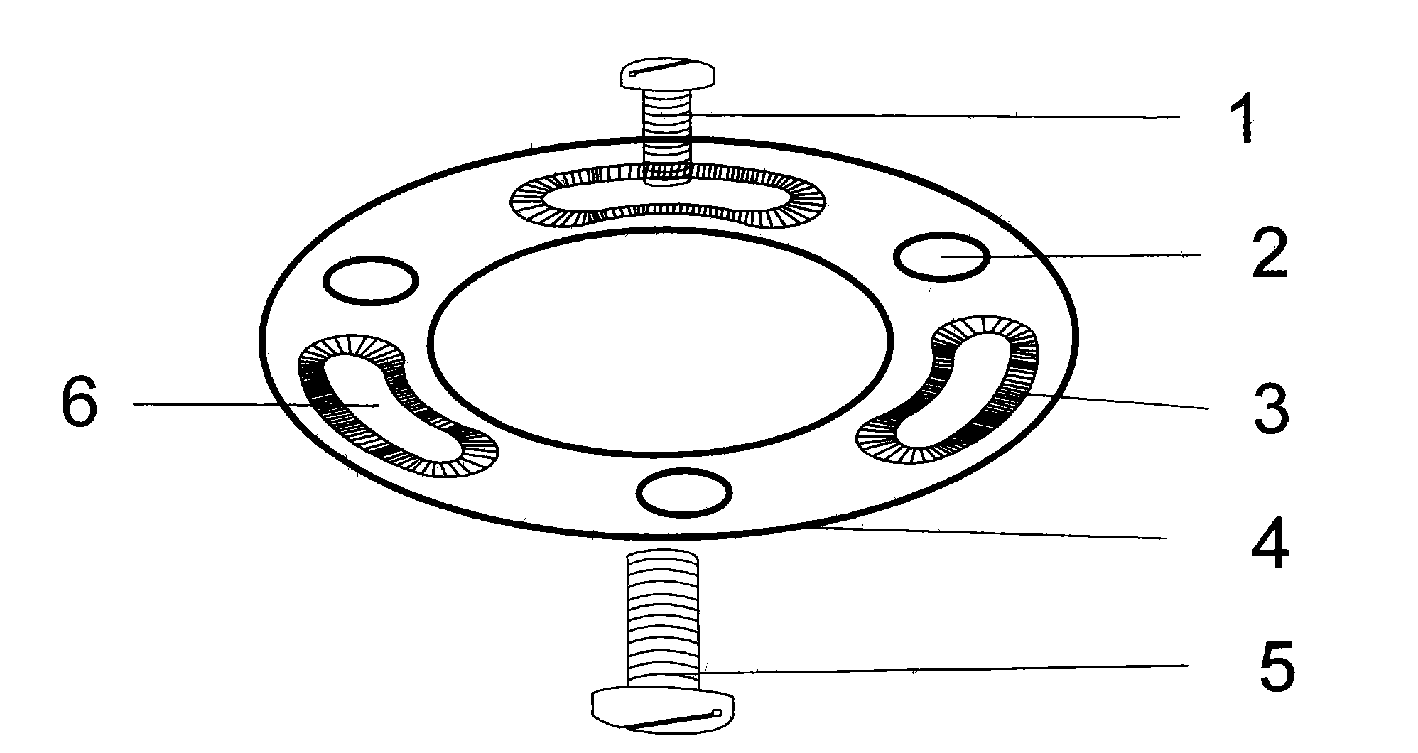
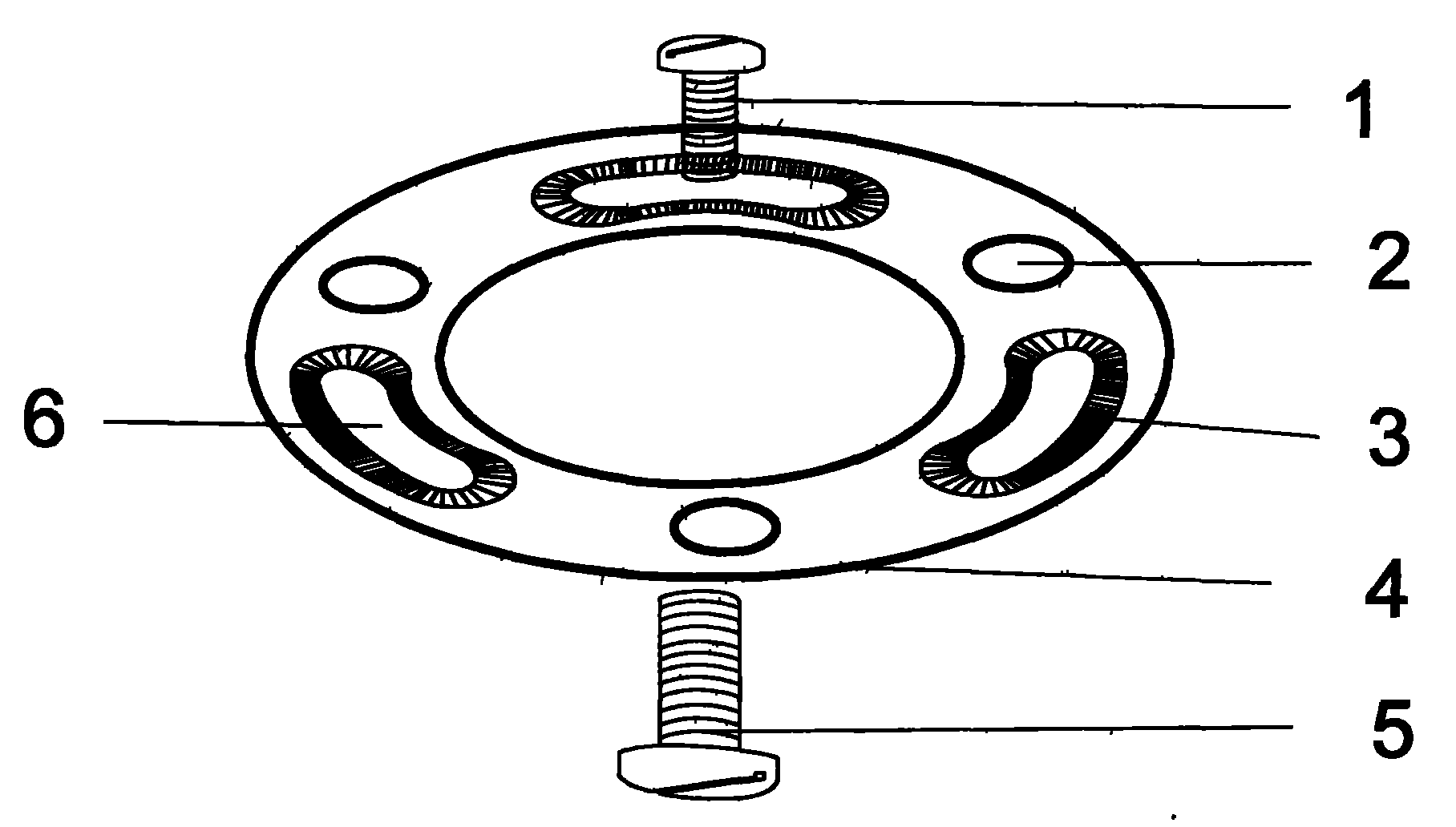
[0010] exist figure 1 Among them, there are three to five screw holes (2) and three to five arc-shaped grooves (3) on a piece of ring-shaped metal or plastic, and there are arc-shaped screw holes (6) in the middle of the arc-shaped grooves, and the arc-shaped screw holes can Go through the bolt of the screw (1), but not the nut of the screw. Put the preparatory screw (1) in the arc-shaped screw hole (6) of the installation ring (4), put the grooved side of the installation ring facing the ceiling, and fix it to the ceiling with the screw (5) through the screw hole (2) After fixing, the preparatory screw (1) can move left and right in the arc groove (3).

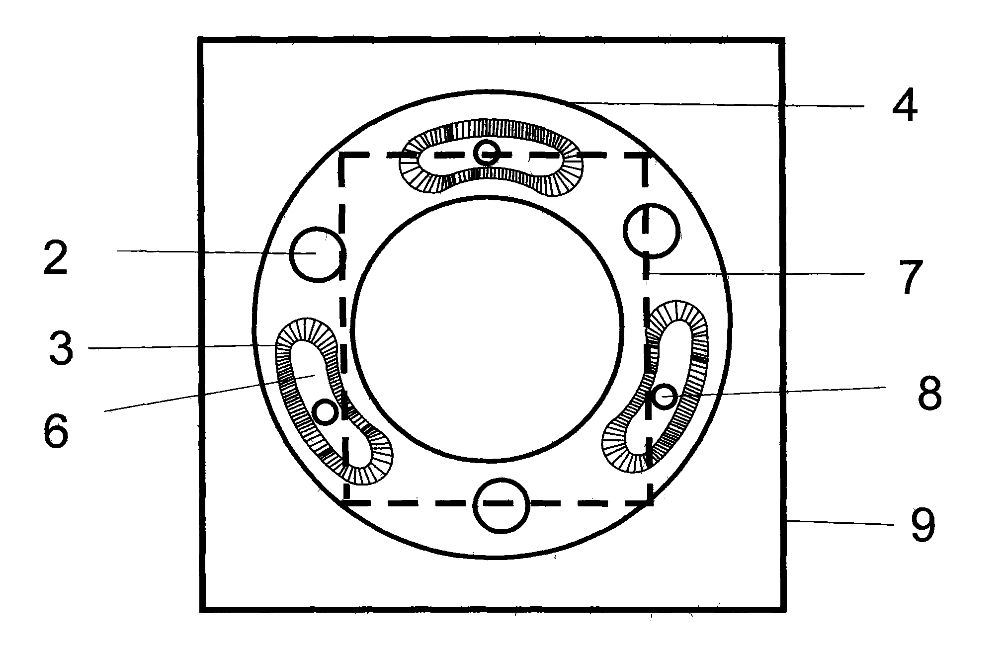
[0011] exist figure 2 In the shown embodiment, there is a square marking line (7) on the protruding side of the installation ring (4). The position is fixed on the ceiling. Then align the ceiling lamp screw hole (8) on the ceiling lamp shell (9) with the preparatory screw (1) on the installation ring, add the washer and ...


PUM


Abstract

The invention discloses an azimuth angle adjustable mounting ring of a square ceiling lamp. An annular metal or plastic is provided with three to five screw holes (2) and three to five arc grooves (3), the middles of the arc grooves are provided with arc screw holes (6), bolts of screws (1) can pass through the arc screw holes, and screw caps of the screws cannot pass through the arc screw holes. Preparatory screws (1) are placed in the arc screw holes (6) of the mounting ring (4), and the preparatory screws can move left and right in the arc grooves (3). One side of the mounting ring with the grooves is fixedly arranged opposite to a ceiling, ceiling lamp screw holes (8) on a ceiling lamp shell (9) are aligned with the preparatory screws (1) on the mounting ring, the screw caps for a gasket are tightened, and the ceiling lamp shell (9) and the screws (1) are rotated at the same time of tightening the screw caps to adjust an ideal azimuth. The mounting ring can quickly adjust the ideal azimuth for mounting the square ceiling lamp.

Description

technical field [0001] The invention relates to a mounting structure of a ceiling lamp, in particular to a mounting bracket with an adjustable angle for a square ceiling lamp. Background technique [0002] At present, the installation of the square ceiling lamp is to dismantle the lampshade first, hold the lamp to the ceiling, mark the screw holes on the ceiling lamp shell, use a percussion drill to drill the holes and place small wooden strips, and then lift the lamp to install the screws. Due to the deviation between the mark made on the ceiling and the drilling of the percussion drill on the prefabricated board, and the deviation between the placement of the small wooden strips and the installation of the screws, it is difficult to install the square ceiling light in a good position at one time. If the position is not good, it will affect the beauty of the ceiling light. Disassembly and re-drilling, installers sometimes have to install a lamp for an hour or two, and the o...

Claims


Application Information

Patent Timeline
Patent Type & Authority Applications(China)
IPC IPC(8): F21V21/00
Inventor 陶国胜
Owner 陶国胜
Why Eureka
Try Eureka