Method of using distributed optical fibers for advanced monitoring of tunnel surrounding rock deformation

A technology of distributed optical fiber and surrounding rock deformation, applied in the direction of measuring devices, optical devices, instruments, etc., can solve the problems of lack of perfect technical means, expensive BOTDR equipment, complex geological conditions, etc.

Active Publication Date: 2011-08-31
CHINA RAILWAY TUNNEL GROUP CO LTD
View PDF3 Cites 50 Cited by
  • Summary
  • Abstract
  • Description
  • Claims
  • Application Information

AI Technical Summary

Problems solved by technology

However, due to the concealment of underground engineering, complex geological conditions, expensive BOTDR equipment, and complicated monitoring system design, BOTDR technology has not been applied to typical underground engineering such as tunnel surrounding rocks.
Especially in the monitoring of the advanced deformation of the tunnel surrounding rock, there is no perfect technical means

Method used


Image

  • Method of using distributed optical fibers for advanced monitoring of tunnel surrounding rock deformation
  • Method of using distributed optical fibers for advanced monitoring of tunnel surrounding rock deformation
  • Method of using distributed optical fibers for advanced monitoring of tunnel surrounding rock deformation

Examples


Embodiment Construction

[0022] The present invention is described in conjunction with embodiment:

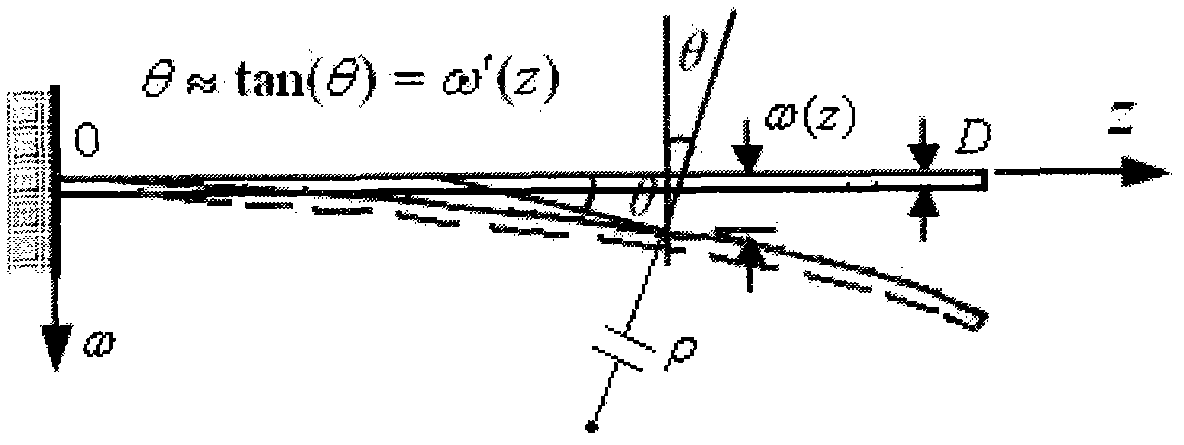
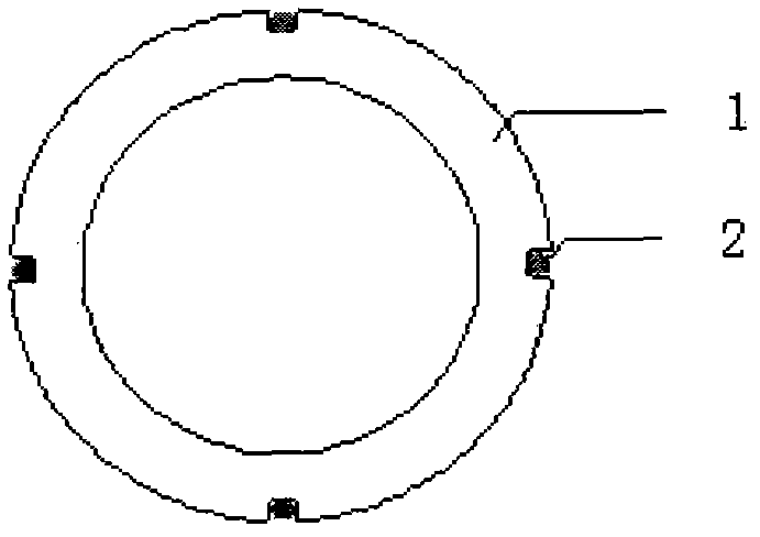
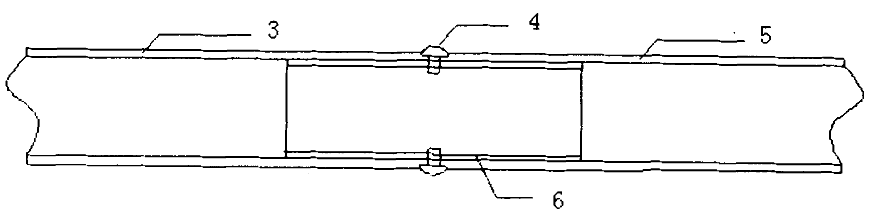
[0023] A distributed optical fiber advanced monitoring method for tunnel surrounding rock deformation. The monitoring device involved in the method consists of distributed optical fiber measuring tubes, optical fiber sensing lines, Brillouin backscattered light data acquisition equipment BOTDR, and data processing and analysis software. Composition; the sensing optical fiber coated with adhesive is arranged symmetrically on the outer surface of the PP-R tube in a fully pasted manner to make a distributed optical fiber measuring tube. By measuring the strain distribution of the optical fiber, according to the mechanical model of the cantilever beam, it is assumed that the measured The displacement of one end of the tube is known, and the two-dimensional deformation distribution along the lateral direction (perpendicular to the length direction of the tube) is calculated; the distributed optical fiber tub...


PUM


Abstract

The present invention provides a method of using distributed optical fibers for an advanced monitoring of tunnel surrounding rock deformation. A monitoring device related to the method comprises a distributed optical fiber measuring pipe, an optical fiber sensing line, a Brillouin backscattering light data acquisition facility, and a data processing and analyzing software. The method comprises the steps of symmetrically laying sensing optical fibers on the external surface of a PP-R pipe to manufacture the distributed optical fiber measuring pipe, by which the displacement of soil along the measuring pipe can be obtained; embedding the distributed optical fiber measuring pipe in the drilling hole in the overlying surrounding rock of the tunnel, and injecting couplant to form a measuring pipe of a soil-pipe compatible deformation type, wherein the measuring pipe deforms with the synchronous displacement of the surrounding rock; and realizing monitoring of the deformation or displacement of the surrounding rock by measuring the deformation of the measuring pipe. The method provided in the invention has the characteristics of a distributed type, automatic data acquisition, real time and advanced monitoring, etc., and is suitable for monitoring surrounding rock two dimensional deformation or displacement in the geotechnical engineering field such as a tunnel cavern, a coal mine tunnel, etc.

Description

technical field [0001] The invention belongs to the technical field of geotechnical engineering monitoring, and relates to a method for distributed optical fiber advanced monitoring of tunnel surrounding rock deformation. Background technique [0002] Our country is in the period of large-scale infrastructure construction. A large number of deep buried and long tunnel projects have appeared in various fields such as transportation, national defense, and water conservancy. Many new problems have emerged in design theory and construction technology, and the risks faced by construction have intensified. During the tunnel construction process, the mechanical properties of the surrounding rock in front of the tunnel excavation face are constantly changing, so the deformation characteristics and development trend of the surrounding rock can be detected in advance, and the stratum displacement information at each deformation stage in front of the tunnel excavation face can be obtain...

Claims


Application Information

Patent Timeline
Patent Type & Authority Applications(China)
IPC IPC(8): G01B11/16G01B11/02
Inventor 施斌尹龙张丹甘宇宽卢毅干昆蓉杨毅任彦超
Owner CHINA RAILWAY TUNNEL GROUP CO LTD
Why Eureka
Try Eureka