Installing and positioning method of linear guide rail

A linear guide rail, installation and positioning technology, applied in the field of mechanical processing and manufacturing, can solve the problems of linear guide rail accuracy reduction, failure to meet the use requirements, etc., achieve the effect of improving efficiency, solving the requirements of process equipment accuracy, and the method is fast and convenient

Inactive Publication Date: 2011-09-14
CHAOYANG BOWEN MACHINE TOOL
View PDF6 Cites 29 Cited by
  • Summary
  • Abstract
  • Description
  • Claims
  • Application Information

AI Technical Summary

Benefits of technology

In this new way that uses an improved system called Linear Guide Rail (LTR) instead of older methods like straight rails, it allows for precise placement during manufacturing processes while reducing assembly times compared with previous systems.

Problems solved by technology

This patented technical solution describes how improving the movement and alignment between two parts (a guided part called an upper track) used for machining tools helps ensure accurate performance during operation without sacrifices over time due to changes made along the way. However, current methods are limited because they require high levels of labor and may result in errors when attaching the mount bases onto the guide rods themselves.

Method used


Image

  • Installing and positioning method of linear guide rail
  • Installing and positioning method of linear guide rail

Examples


Embodiment Construction

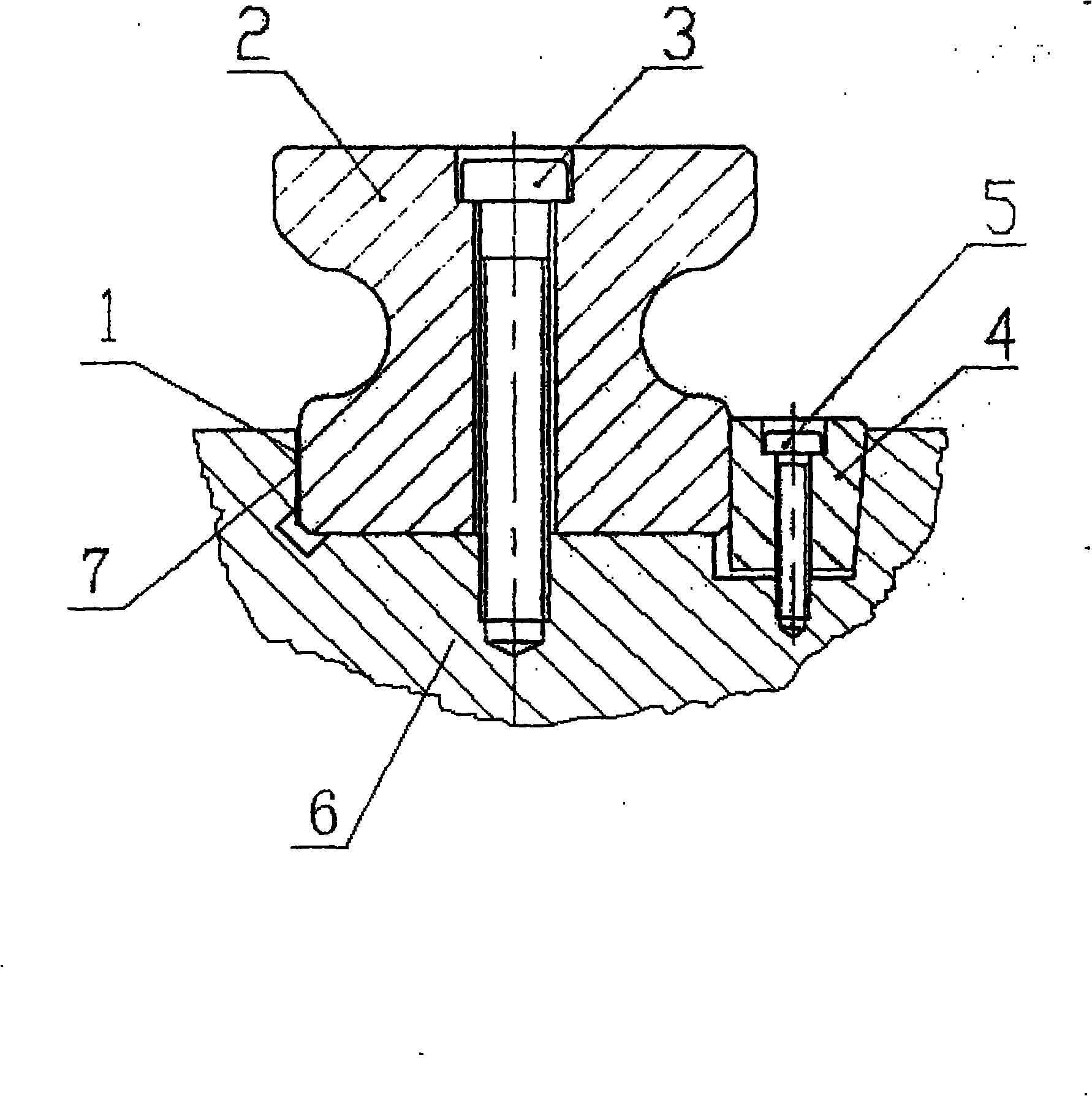
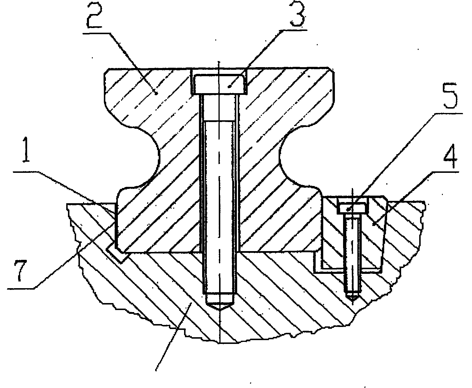
[0017] Referring to the accompanying drawings, taking the MK2860 CNC internal grinding machine as an example, the installation and positioning method of the linear guide rail is carried out in the following steps:

[0018] 1) First confirm a linear guide rail as the reference guide rail, and confirm the installation reference surface of the guide rail, and place the linear guide rail 2 on the installation reference surface of the base 6, so that the guide rail installation base surface and the base installation base surface correspond to each other;

[0019] 2) Install the guide rail screw 3 to make the guide rail in step 1) slightly tightened with strength, and then calibrated by the micrometer calibration table, gradually tighten the guide rail screw 3 from one end along the guide rail 2, so that the straightness of the guide rail is guaranteed within the accuracy requirement range;

[0020] 3) On the side of the guide rail 2 and between the vertical side reference plane of t...


PUM


Abstract

The invention discloses an installing and positioning method of a linear guide rail. The method comprises the following steps of: first determining a reference guide rail and an installation reference surface of the guide rail, flatly placing the guide rail on the installation reference surface of a base so that the guide rail corresponds to the installation reference surface of the base; installing a guide rail screw and enabling the guide rail to be slightly screwed up, and tightly screwing up the guide rail after correcting to ensure that the precision of the guide rail is in a required range; at one side of the guide rail, injecting positioning glue into a gap between the vertical-side reference surface of the base and the corresponding basal plane at the guide rail side to fill the gap; after the positioning glue is cured, placing a wedge block in a positioning groove at the other side of the guide rail and tightly screwing up a welding block screw to compress the guide rail; and regulating and fixing the other linear guide rail according to the same method. The installing and positioning method disclosed by the invention completely replaces the traditional installing and positioning method of the linear guide rail; and by means of the installing and positioning method disclosed by the invention, the requirement for the precision in the process of machining the base reference surface is met, the installation and regulation time of the guide rail is shortened to half a day from original three months, and the requirements on the linear guide rail for all precision levels can be completely met.

Description


Claims


Application Information

Patent Timeline
Owner CHAOYANG BOWEN MACHINE TOOL
Why Eureka
Try Eureka