Injection-moulding mould for in-mould transfer printing

An injection mold, in-mold transfer technology, applied in the direction of coating, etc., can solve the problems of easy blockage of vent holes, slow suction speed, and easy wrinkles of transfer film

Active Publication Date: 2011-09-28
汕头市澄海区雄城塑胶玩具有限公司
View PDF6 Cites 28 Cited by
  • Summary
  • Abstract
  • Description
  • Claims
  • Application Information

AI Technical Summary

Problems solved by technology

However, the existing in-mold transfer injection molds still have disadvantages such as slow suction speed, easy wrinkling of the transfer film, and easy blockage of the vent holes.

Method used


Image

  • Injection-moulding mould for in-mould transfer printing
  • Injection-moulding mould for in-mould transfer printing
  • Injection-moulding mould for in-mould transfer printing

Examples


Embodiment Construction

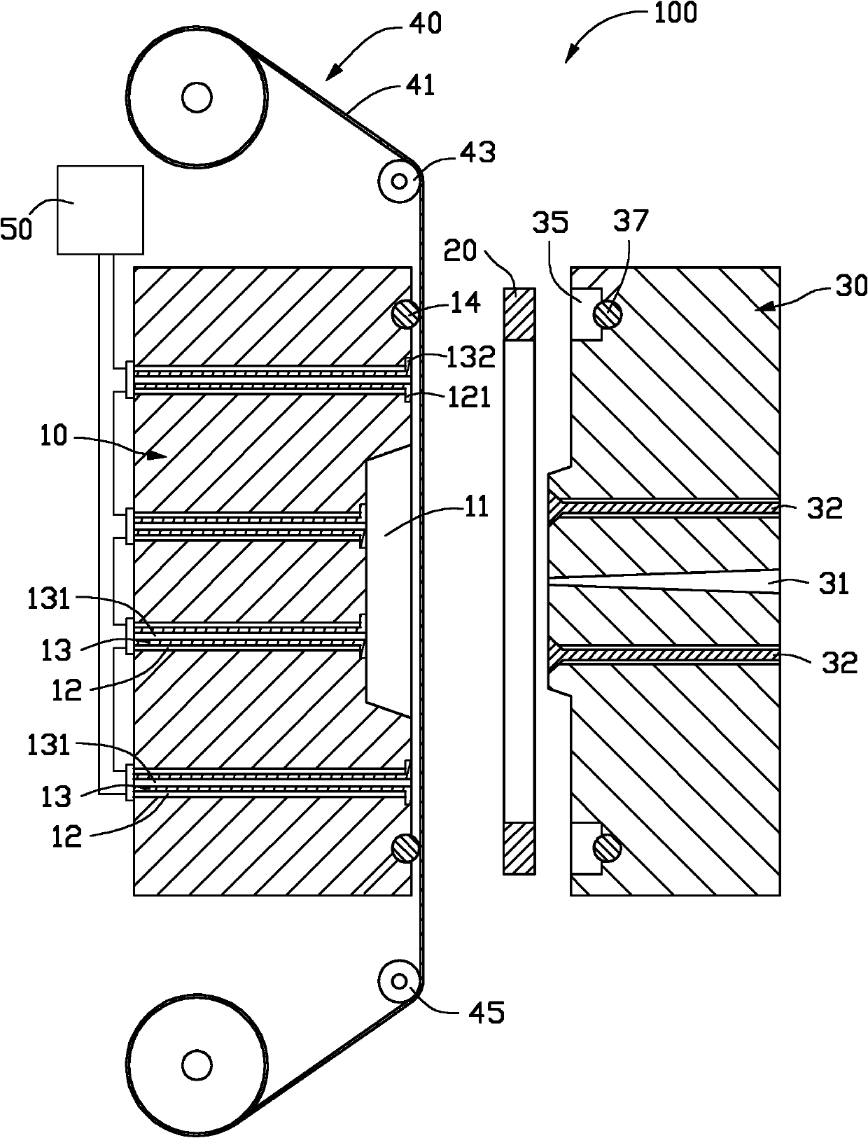
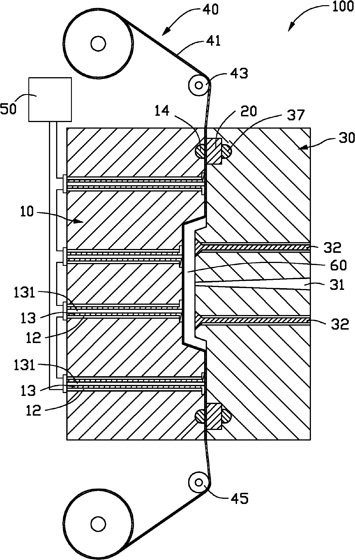
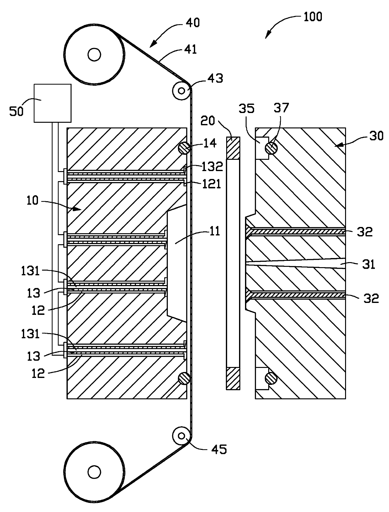
[0011] see figure 1 and figure 2 , the in-mold transfer injection mold 100 according to the embodiment of the present invention includes a female mold 10 , a pressing plate 20 , a male mold 30 , a film feeding device 40 and an exhaust device 50 . A transfer film 41 can be accommodated between the pressing plate 20 and the master mold 10 , and the transfer film 41 is fed by the film feeding device 40 . The pressing plate 20 is disposed between the female mold 10 and the male mold 30 for pressing the transfer film 41 . The female mold 10 and the male mold 30 together form a cavity 60 . When the plastic material fills the cavity 60 to form a plastic part, the decorative pattern on the transfer film 41 can be transferred to the plastic part.

[0012] The master mold 10 defines a mold cavity 11 and a plurality of vent holes 12 . The exhaust hole 12 runs through the master mold 10 and communicates with the cavity 60 . One end of the exhaust hole 12 away from the cavity 60 is c...


PUM


Abstract

The invention discloses an injection-moulding mould for in-mould transfer printing. The injection-moulding mould comprises a female mould, a laminated plate, a male mould and a gas exhausting device, wherein a transfer printing film can be accommodated between the laminated plate and the male mould; the laminated plate can press the transfer printing film; the female mould and the male mould form a cavity; when the cavity is filled with plastic to form a plastic component, ornamental patterns on the transfer printing film can be transferred to the plastic component; a gas exhausting hole which is communicated with the cavity is formed on the female mould; a gas exhausting component is fixedly arranged in the gas exhausting hole; a gas pumping hole which is communicated with the cavity and the gas exhausting hole is formed on the gas exhausting component; and the gas exhausting device is connected with the gas exhausting hole and is used for pumping out the gas in the cavity so as to attract the transfer printing film towards the surface of the female mould. The injection-moulding mould can reduce the creases of the transfer printing film and make the transfer printing film adhere to the surface of the female mould uniformly.

Description

technical field [0001] The invention relates to an in-mold transfer printing injection mold. Background technique [0002] In-mold transfer injection molding is a process that simultaneously completes the molding and surface decoration of injection molded parts. The decorative pattern to be transferred is pre-formed on a transfer film by printing or vapor deposition, and then the transfer film is placed on the male mold. Between the mold and the master mold, after the mold is closed, the plastic is injected into the mold to form a plastic part, and the decorative pattern is transferred to the surface of the plastic part at the same time. After the plastic is cured, the plastic part is ejected to form a decorative pattern. plastic parts. [0003] An existing in-mold transfer printing injection mold includes a female mold, a pressing plate and a male mold. A transfer film can be accommodated between the pressing plate and the master mold, and the pressing plate can hold the ...

Claims


Application Information

Patent Timeline
Patent Type & Authority Applications(China)
IPC IPC(8): B29C45/26B29C45/34B29C45/14
Inventor 王国志
Owner 汕头市澄海区雄城塑胶玩具有限公司
Why Eureka
Try Eureka