
System and method for fault isolation of abnormal light emission of optical network unit

An optical network unit and network unit technology, applied in the field of optical networks, can solve the problems of economic loss, PON paralysis or interruption, and high luminous power, and achieve the effects of reducing costs and improving stability and reliability.

Active Publication Date: 2016-07-06
ZTE CORP
View PDF8 Cites 0 Cited by
  • Summary
  • Abstract
  • Description
  • Claims
  • Application Information

AI Technical Summary

Problems solved by technology

There are obviously hidden dangers of faults here. For example, if an ONU fails to obey the command of the OLT, or artificially puts a light source on a certain ONU, then two or more Two or more ONUs are emitting light. Since their wavelengths are the same, the OLT cannot distinguish the difference at all, and it will think that one ONU is emitting light. Saturation state, in addition, because the long-lighting ONUs exist in all time periods, the communication between all ONUs and the OLT will soon be in an abnormal working state, and the PON will fall into a paralyzed or interrupted state, which will affect the operation It is a very serious operation incident for the business, and it will also cause very serious consequences and economic losses

Method used


Image

  • System and method for fault isolation of abnormal light emission of optical network unit
  • System and method for fault isolation of abnormal light emission of optical network unit
  • System and method for fault isolation of abnormal light emission of optical network unit

Examples


Embodiment Construction

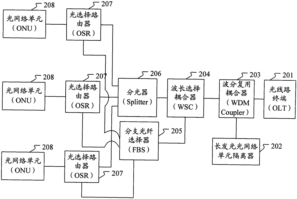
[0043] The basic idea of ​​the present invention is: on the basis of the existing passive optical network, some active and passive optical functional modules are added, so that when an uncontrollable long-emitting optical network unit occurs, the optical line terminal and the normal On the premise that the communication between the optical network units remains unimpeded, timely isolate the optical network units that emit light abnormally.

[0044] figure 2 It is a schematic structural diagram of the fault isolation system for abnormal light emission of the optical network unit of the present invention, such as figure 2 As shown, the optical network unit abnormal lighting fault isolation system of the present invention includes: optical line terminal 201, long-lighting optical network unit isolator 202, wavelength division multiplexing coupler 203, wavelength selective coupler 204, branch fiber selector 205, optical splitter device 206, optical selection router 207 and opti...


PUM


Abstract

The invention discloses a fault isolation system for abnormal light emission of an optical network unit, which comprises: an optical line terminal, a long light emission optical network unit isolator, a wavelength division multiplexing coupler, a wavelength selective coupler, a branch fiber selector, an optical splitter, an optical Choose routers and optical network units. When an uncontrollable long-emitting optical network unit occurs, the abnormally luminous optical network unit can be isolated in time under the premise that the communication between the optical line terminal and the normal optical network unit remains smooth. The invention also correspondingly discloses a method for isolating abnormal lighting faults of optical network units. Because the present invention can isolate the long-emitting optical network unit from the passive optical network in time, it can ensure that other users can still communicate normally during the maintenance period of the abnormally luminous and faulty optical network unit, thereby improving the stability of the passive optical network and reducing the operating time. and maintenance costs.

Description

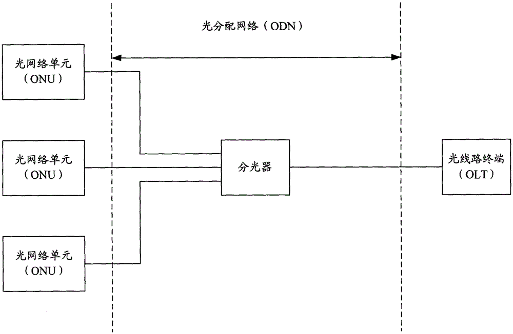
technical field [0001] The invention relates to optical network technology, in particular to a system and method for isolating an abnormal light emitting fault of an optical network unit. Background technique [0002] With the rapid development of optical fiber communication technology, optical fiber for wired broadband access is gradually replacing the existing copper wire (wired) system, and it has become a trend that light enters copper and retreats. Due to the characteristics of high speed and environmental protection of the passive optical network, the passive optical network has been widely used to meet the increasing communication users and higher service requirements. [0003] Passive optical network is a point-to-multipoint optical fiber access technology. figure 1 It is a schematic diagram of the structure of the existing passive optical network, such as figure 1 As shown, the passive optical network includes an optical line terminal (OpticalLineTerminal, OLT), a...

Claims


Application Information

Patent Timeline
Patent Type & Authority Patents(China)
IPC IPC(8): H04B10/032H04Q11/00H04J14/02
CPCH04L41/06
Inventor 徐继东
Owner ZTE CORP
Learn More