Supercharge Your Innovation With Domain-Expert AI Agents!

Light guide element for a lighting device

A technology of light guide components and lighting devices, which can be used in lighting devices, fixed lighting devices, optical components, etc., and can solve high-risk problems

Active Publication Date: 2014-01-08
GERG LIGHTHOUSE GMBH
View PDF6 Cites 0 Cited by
  • Summary
  • Abstract
  • Description
  • Claims
  • Application Information

AI Technical Summary

Problems solved by technology

While on average only a quarter of traffic accidents occur at night, the risk of fatal traffic accidents is twice as high at night than during the day

Method used


Image

  • Light guide element for a lighting device
  • Light guide element for a lighting device
  • Light guide element for a lighting device

Examples


Embodiment Construction

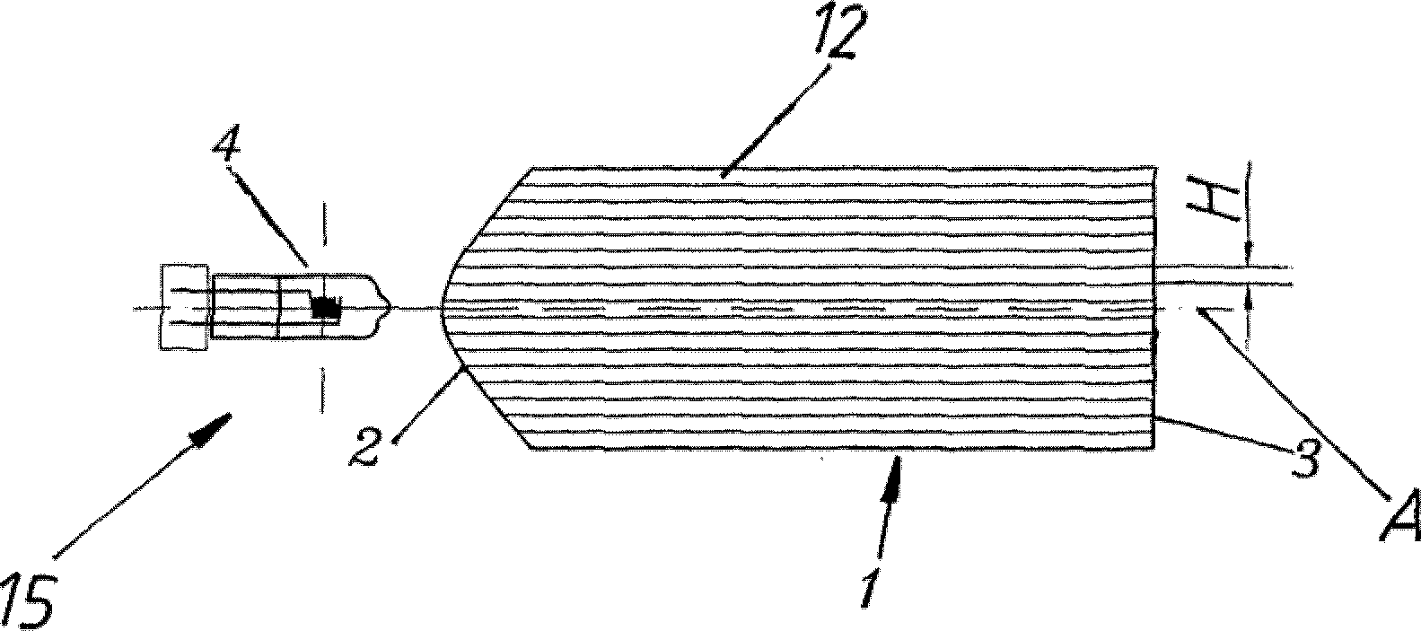
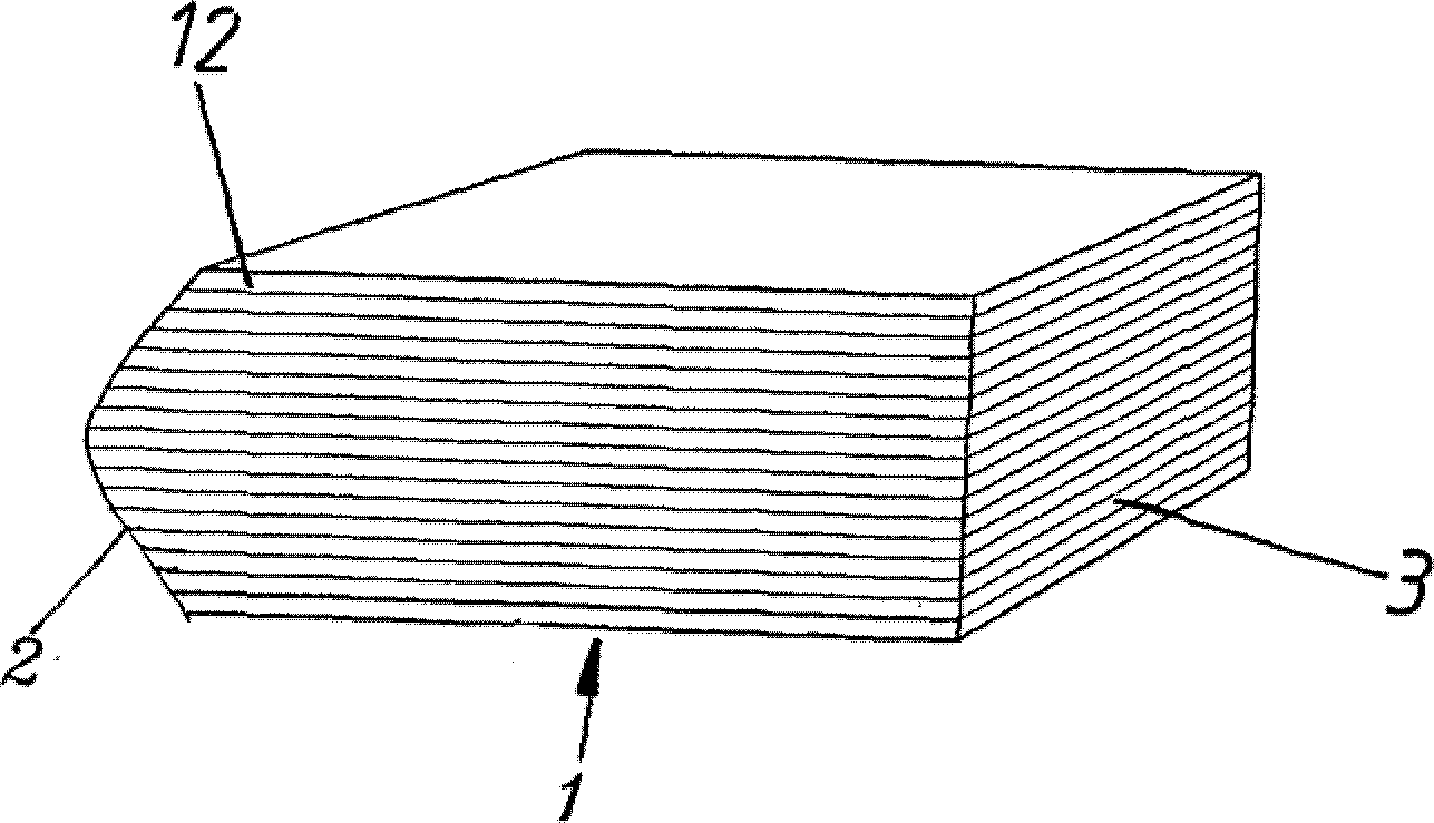
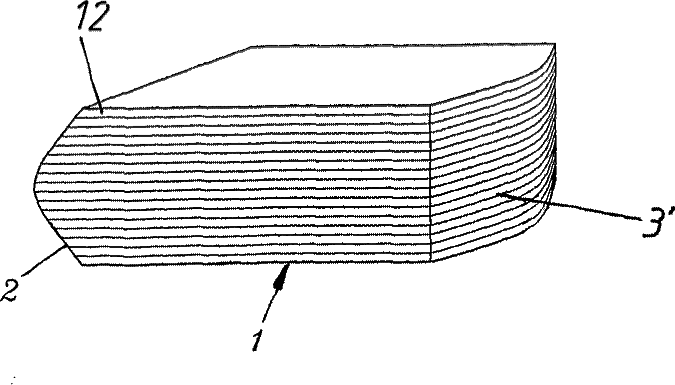
[0055] Figure 1aA cross section of an inventive lighting device 15 with light guide element 1 and associated light source 4 is shown, perpendicular to the surface of the light guide element 1 , through the light guides 12 forming the light guide element 1 placed one above the other. The light-guiding element 1 consists of a light guide 12 in sheet form. The individual light guides 12 have essentially the same height H here. The light-guiding element 1 is in the direction of the main axis A, which is arranged at the geometric center (here the center of gravity) of the planarized exit surface 3 and parallel to the longitudinal edges of the light guide 12 . The light guide 12 has a rectangular cross-section except at the aspherically ground entrance surface 2 . The entrance surface 2 has an aspheric ground which fulfills the function of a lens by focusing the incoming light rays. Figure 1b A perspective view of a light guide element 1 with light guides 12 stacked one above t...


PUM


Abstract

A light guide element for a lighting device is elongated in the direction of a main axis and includes a light coupling surface extending transversely to the longitudinal direction and a light emission surface radiating transversely to the longitudinal direction, and two or more light guides stacked on top of one another, wherein a partial region of the wall of the individual light guides extending in the longitudinal direction is structured and / or blackened.

Description

technical field [0001] The invention relates to a light guide element for a lighting device. Background technique [0002] An example of such a light guide element is given in DE202007003497U1. [0003] A disadvantage of the light guide elements known in this and other prior art is that the light exits the light guide element unevenly and, despite all efforts, cannot be separated between bright illuminated areas and dark unilluminated areas. A precise demarcation is achieved such that vehicle headlights equipped with such light guide elements dazzle oncoming motorists. [0004] Dazzling people looking in the direction of lighting fixtures is a big problem in various everyday areas of life. In addition to the glare that occurs in road traffic, this problem also concerns road lighting, for example for tunnel lighting, lighting of public areas such as stadiums, lighting of work areas or dwellings, etc. Although on average only a quarter of traffic accidents occur at night, t...

Claims


Application Information

Patent Timeline
Patent Type & Authority Patents(China)
IPC IPC(8): B60Q1/00F21S8/12G02B27/09G02B6/00
CPCB66F9/08G02B27/09
Inventor G·康扎蒂H·韦恩格特纳P·斯瓦洛夫斯基
Owner GERG LIGHTHOUSE GMBH
Features
  • R&D
  • Intellectual Property
  • Life Sciences
  • Materials
  • Tech Scout
  • Unparalleled Data Quality
  • Higher Quality Content
  • 60% Fewer Hallucinations
Learn More