Heat exchanger with improved heat exchange performance

A technology for heat exchangers and heat exchange tubes, applied in the direction of heat exchanger shells, heat exchange equipment, evaporators/condensers, etc., can solve problems such as adverse effects on heat exchange performance of heat exchangers, and achieve good heat exchange capacity, The effect of uniform flow rate and improved overall efficiency

Active Publication Date: 2011-11-02
SANHUA(HANGZHOU) MICRO CHANNEL HEAT EXCHANGER CO LTD
View PDF3 Cites 20 Cited by
  • Summary
  • Abstract
  • Description
  • Claims
  • Application Information

AI Technical Summary

Problems solved by technology

[0004] Although the heat transfer performance of the heat exchanger can be enhanced by fins, the heat transfer performance of the traditional heat exchanger may be adversely affected by various factors, so further improvement is still needed

Method used


Image

  • Heat exchanger with improved heat exchange performance
  • Heat exchanger with improved heat exchange performance
  • Heat exchanger with improved heat exchange performance

Examples


Embodiment Construction

[0052] Embodiments of the present invention are described in detail below, examples of which are shown in the drawings, wherein the same or similar reference numerals designate the same or similar elements or elements having the same or similar functions throughout. The embodiments described below by referring to the figures are exemplary only for explaining the present invention and should not be construed as limiting the present invention.

[0053] In the description of the present invention, the orientation or positional relationship indicated by the terms "inner", "outer", "longitudinal", "transverse", "upper", "lower" etc. are based on the orientation or positional relationship shown in the drawings, The disclosure is merely for convenience in describing the invention and does not require that the invention must be constructed and operated in a particular orientation, and thus should not be construed as limiting the invention.

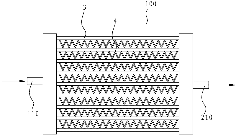
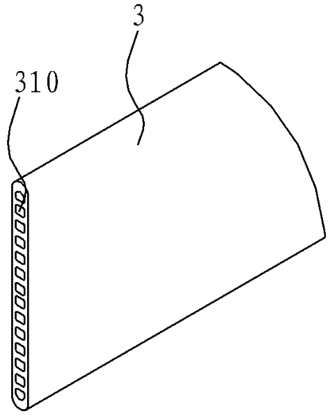
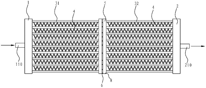
[0054] Refer below Figure 1-Figure 21 A h...


PUM


Abstract

The invention discloses a heat exchanger comprising a first collecting pipe, a second collecting pipe, heat exchange pipes and fins, wherein the second collecting pipe and the first collecting pipe are spaced; a refrigerant path is confined in each heat exchange pipe; two ends of each heat exchange pipe are respectively connected with the first collecting pipe and the second collecting pipe to communicate the first collecting pipe with the second collecting pipe via the refrigerant path; the total cross section area of the refrigerant paths of the heat exchange pipes is changed along the flowing direction of the refrigerant in the heat exchange pipes so as to cause the flowing rate of the refrigerant to be coincident with the flowing direction of the refrigerant; and the fins are arranged between the adjacent heat exchange pipes. According to the heat exchanger disclosed by the embodiment of the invention, the total cross section area of the heat exchange pipes on the inlet side and outlet side of the refrigerant changes along with the state of the refrigerant, so that the refrigerant flows in the heat exchange pipes and maintains relatively even flowing rate, thereby improving the integral efficiency of the heat exchanger so as to better perform the heat exchange capability of the heat exchanger.

Description

[0001] This application is a divisional application with the application number 201010215929.8, the filing date is June 29, 2010, and the invention title is "Heat Exchanger with Improved Heat Exchange Performance". technical field [0002] The invention relates to the technical field of refrigeration, in particular to a heat exchanger. Background technique [0003] Traditional heat exchangers usually include headers, fins, and heat exchange tubes, in which the refrigerant flows inside the headers and heat exchange tubes, and the air flows on the outer surface of the heat exchanger, thereby realizing the separation between the refrigerant and the air. The heat exchange between them, and the heat exchange between the refrigerant and the air is enhanced through the fins. [0004] Although the heat transfer performance of the heat exchanger can be enhanced through the fins, the heat transfer performance of the conventional heat exchanger may be adversely affected by various fact...

Claims


Application Information

Patent Timeline
Patent Type & Authority Applications(China)
IPC IPC(8): F25B39/00F28F9/02F28F9/24
Inventor 蒋建龙汪峰黄宁杰
Owner SANHUA(HANGZHOU) MICRO CHANNEL HEAT EXCHANGER CO LTD
Why Eureka
Try Eureka