AIr conditioner flow divider

A shunt and air conditioner technology, which is applied to the details of space heating and ventilation, heating methods, lighting and heating equipment, etc. Heat exchange capability, easy positioning, wide range of effects

Inactive Publication Date: 2004-10-06
HAIER GRP CORP +1
View PDF0 Cites 3 Cited by
  • Summary
  • Abstract
  • Description
  • Claims
  • Application Information

AI Technical Summary

Problems solved by technology

[0003] The purpose of this invention is to solve the problem that the heat exchange capacity of the evaporator cannot be fully exerted due to the uneven distribution of the refrigerant

Method used


Image

  • AIr conditioner flow divider
  • AIr conditioner flow divider
  • AIr conditioner flow divider

Examples


Embodiment Construction

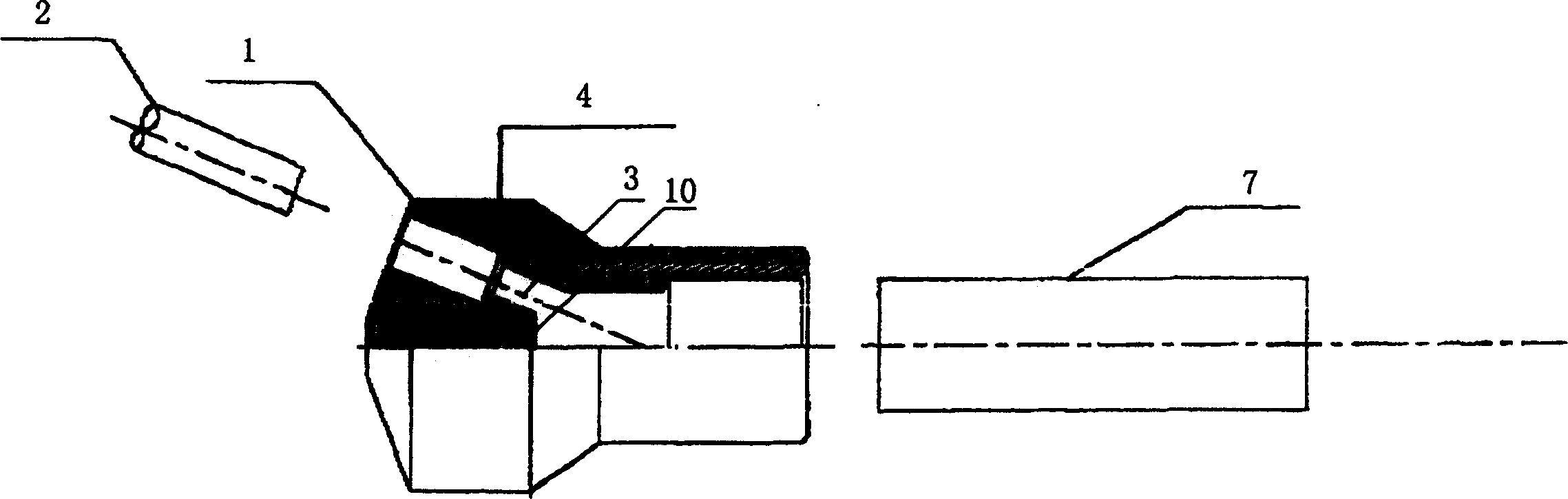
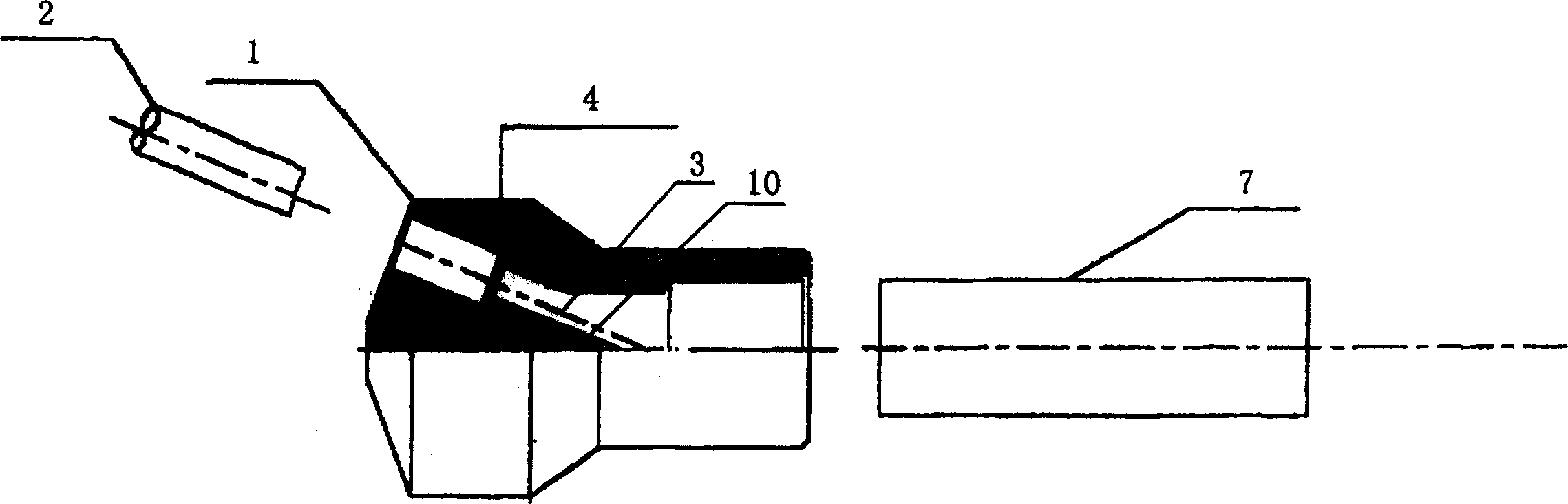
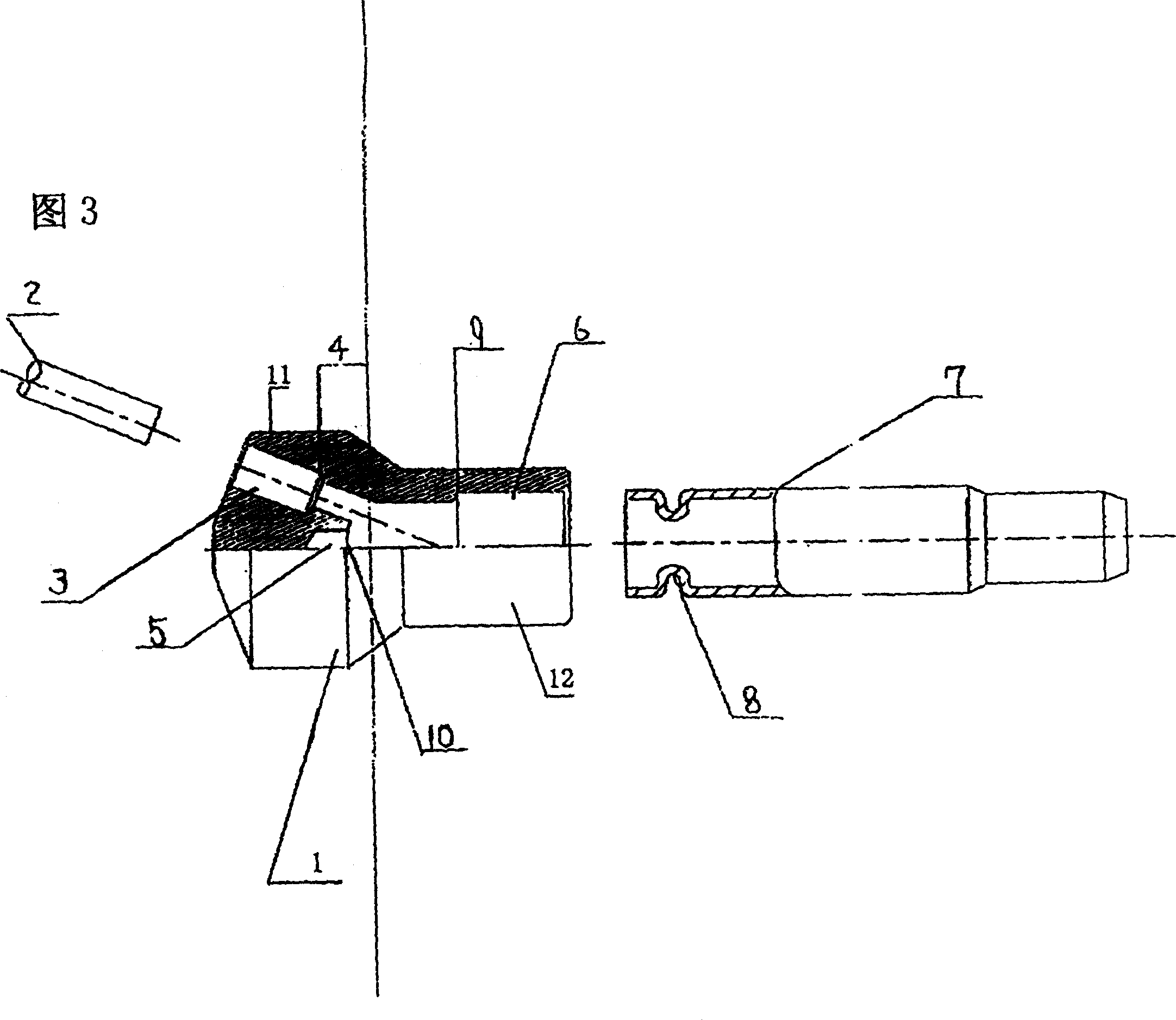
[0019] Referring to FIG. 3, it is a half-sectional view of the liquid distribution head of the air conditioner flow divider of the present invention. As shown in FIG. 3 , the bottom surface of the cavity of the liquid distributor 1 is a groove 5 , and the liquid distributor 1 is composed of a head 11 and a cylinder 12 . There are multiple liquid distribution holes 3 in the head 11 of the liquid distribution head to form a multi-way shunt, such as four-way shunt, the distribution holes 3 are evenly distributed on the arc of the head 11 of the liquid distribution head, and the liquid distribution holes 3 are variable diameters. For the hole, the aperture near the outside is large, and the aperture in the inside is small, and the branch pipe 2 can be inserted into the large hole to the variable diameter part 4 for positioning.

[0020] An inner groove 5 is arranged on the bottom surface of the inner cavity of the liquid-dispensing head 1, and the inner groove 5 is arranged in the...


PUM


Abstract

A flow divider for the indoor unit of air conditioner is composed of the liquid dividing head with at least more than two liquid dividing holes and the connecting tube connected to the liquid inlet of said liquid dividing head. An internal recess is made on the bottom of the internal cavity in liquid dividing head. The level of said internal recess's opening is lower than or equal to the inlet level of liquid dividing hole.

Description

technical field [0001] The invention relates to a splitter of an air conditioner, in particular to the improvement of the structure of the liquid splitter and the connecting pipe of the existing splitter of an air conditioner. Background technique [0002] The air conditioner indoor unit is equipped with an air conditioner splitter. The inlet of the air conditioner splitter liquid head is usually connected with a connecting pipe as the liquid inlet pipe, and the outlet is generally 3-4 branch pipes. The other end of each branch pipe is connected to the On the evaporator, its function is that the refrigerant is evenly distributed here, so that the evaporator can exchange heat evenly and give full play to the heat exchange capacity of the heat exchanger. Existing dispensers such as figure 1 and figure 2 As shown, the middle part of the inner surface of the liquid dispensing head 1 is a plane 13 or a protruding conical surface 14, and the dispensing holes 3 are arranged arou...

Claims


Application Information

Patent Timeline
Patent Type & Authority Applications(China)
IPC IPC(8): F24F13/00
Inventor 楚人震谷东照丁大伟陈启明刘建刚王军
Owner HAIER GRP CORP
Why Eureka
Try Eureka