Box structure for filter

A box structure and filter technology, applied in the fields of dispersed particle filtration, chemical instruments and methods, separation methods, etc., can solve the problem of polluting the downstream space of the filter, and achieve the effect of saving production consumables and improving productivity.

Active Publication Date: 2011-11-23
康斐尔过滤设备太仓有限公司
View PDF5 Cites 2 Cited by
  • Summary
  • Abstract
  • Description
  • Claims
  • Application Information

AI Technical Summary

Problems solved by technology

[0002] At present, the common filter products on the market mostly adopt the structure that the filter partition protrudes from the wall of the box to block the vent and the clean room, and the filter partition separates the half surface of the box wall near the vent and the clean room. Close to the half surface of the clean room, the half surface of the box wall close to the vent blocks the vent and the clean room, and the half of the box wall close to the clean room blocks the clean room and the clean room. The pressure downstream of the filter (that is, the clean room) and the pressure inside the clean room are greater than the pressure outside the clean room, and the baffle structure for installing a fixed filter is installed on the partition of the box, so the seal between the upstream and downstream of the filter must be done well. Otherwise, the unfiltered air upstream of the filter will directly enter the space downstream of the filter through the unsealed gap at the fixed baffle on the box partition, polluting the space downstream of the filter

Method used


Image

  • Box structure for filter
  • Box structure for filter
  • Box structure for filter

Examples


Embodiment

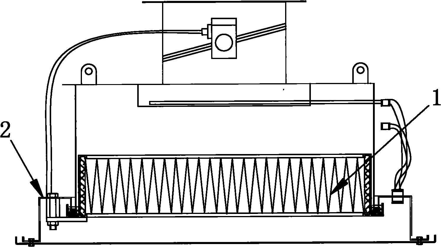
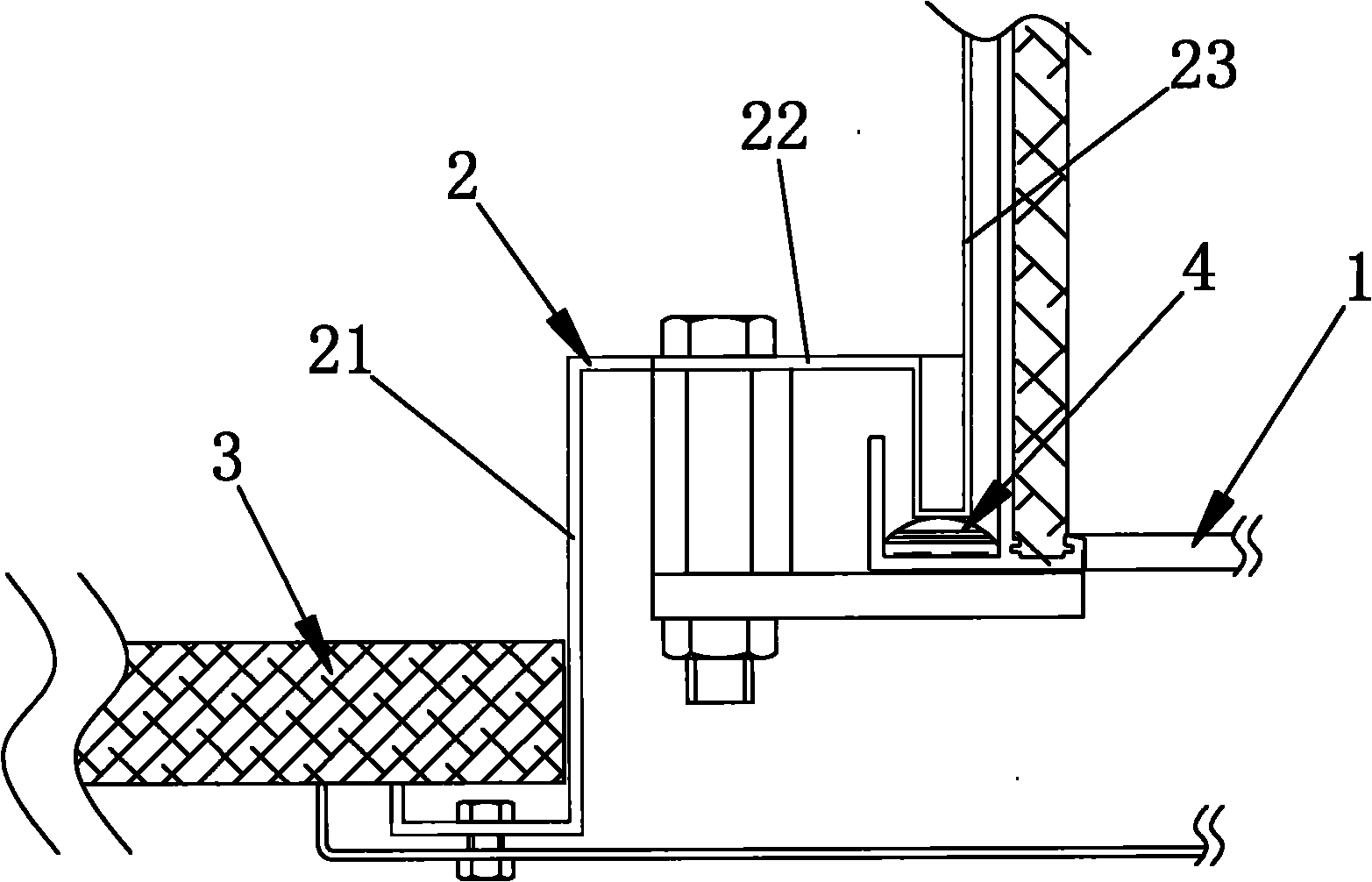
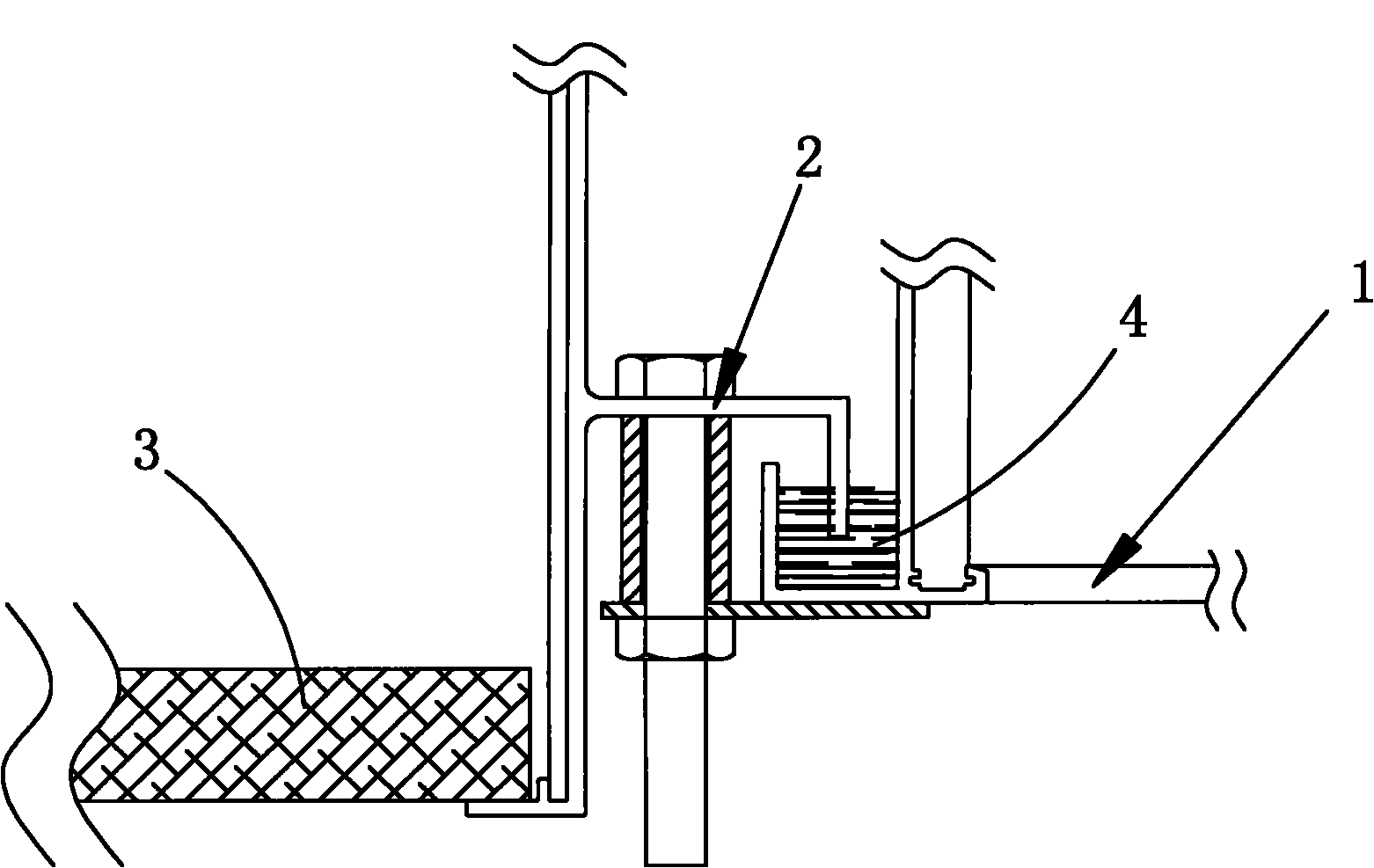
[0010] Embodiment: A box structure of a filter, including a box partition 2, the filter is sealed and positioned on the box partition 2 through a sealing material 4, based on the use direction, the back of the filter 1 faces the clean room, the front of the filter 1 faces the vent, and the box partition 2 is composed of a wall partition 21, a horizontal partition 22 and a filter partition 23, and the wall partition 21 is fixedly connected to the clean room wall Body 3, the filter 1 is sealed and positioned on the filter partition 23, the wall partition 21 and the filter partition 23 are transitionally connected by a horizontal partition 22, and the box partition 2 is integrally bent The filter partition 23 is a double-layer partition formed by bending the side of the horizontal partition 22 close to the filter toward the back of the filter 1, then bending away from the wall, and then bending toward the front of the filter 1. plate, the filter partition 23 blocks the filter and...


PUM


Abstract

The invention discloses a box structure for a filter. In the box structure, a filter is hermetically positioned on a box separator through a sealing material, the back side of the filter faces to a cleaning chamber, and the front side of the filter faces to a ventilating port; the box separator consists of a wall separator, a horizontal separator and a filter separator, the wall separator is fixedly connected to the wall of the cleaning chamber, the filter is hermetically positioned on the filter separator, and the wall separator and the filter separator are in transitional connection by virtue of the horizontal separator; the box separator is formed by virtue of integral bending; the filter separator is a two-layer separator formed by bending, one side, close to the filter, of the horizontal separator toward the back part of the filter, then bending the side toward the direction opposite to the wall, and finally bending the side toward the front side of the filter; the filter separator separates the filter and the outside of the cleaning chamber, so that the sealing property of the horizontal separator is not good due to the requirement of assembling a baffle structure, only air in the cleaning chamber escapes out of the cleaning chamber, and the air cleanness in the cleaning chamber cannot be influenced; and the box separator is formed by virtue of integral bending, so that the production material is saved, and the productivity is improved.

Description

technical field [0001] The invention relates to the field of filter installation structures, in particular to a filter box structure. Background technique [0002] At present, the common filter products on the market mostly adopt the structure that the filter partition protrudes from the wall of the box to block the vent and the clean room, and the filter partition separates the half surface of the box wall near the vent and the clean room. Close to the half surface of the clean room, the half surface of the box wall close to the vent blocks the vent and the clean room, and the half of the box wall close to the clean room blocks the clean room and the clean room. The pressure downstream of the filter (that is, the clean room) and the pressure inside the clean room are greater than the pressure outside the clean room, and the baffle structure for installing a fixed filter is installed on the partition of the box, so the seal between the upstream and downstream of the filter m...

Claims


Application Information

Patent Timeline
Patent Type & Authority Applications(China)
IPC IPC(8): B01D46/00
Inventor 葛雯
Owner 康斐尔过滤设备太仓有限公司
Why Eureka
Try Eureka