Single-shaft horizontally-arranged variable-track vibration exciter

A vibrator, variable technology, applied in the direction of the fluid using vibration, can solve the problems of limited eccentric force excitation force, large space, inconvenient adjustment of direction angle, etc., to achieve enhanced vibration balance and strong motion balance Effect

Inactive Publication Date: 2013-05-08
ZHEJIANG SHENGDA MACHINERY
View PDF9 Cites 0 Cited by
  • Summary
  • Abstract
  • Description
  • Claims
  • Application Information

AI Technical Summary

Problems solved by technology

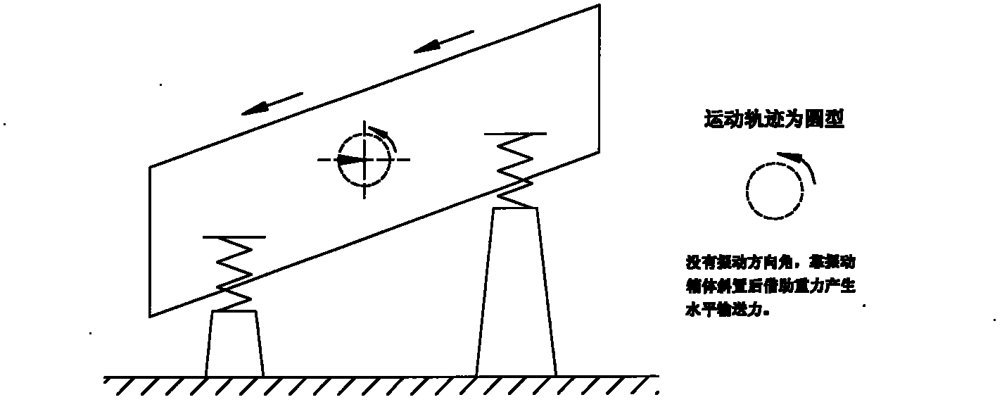
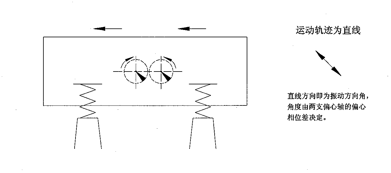
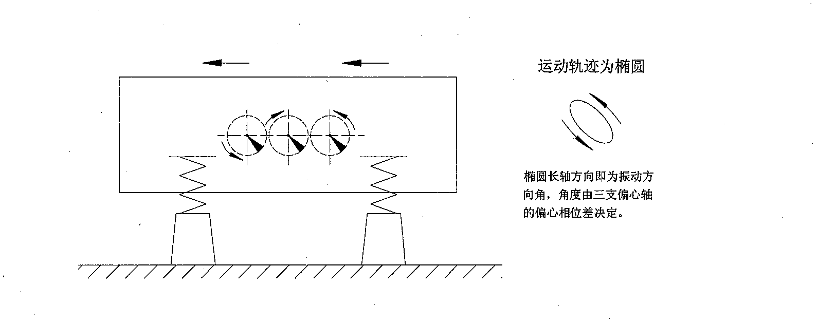
Therefore, the vibrator does not realize the conversion of the three motion trajectories of circle, straight line and ellipse in a practical sense.
②. It is inconvenient to adjust the direction angle
③. Due to the limitation of the structure of the motor, the eccentric force (that is, the exciting force) of the exciter is very limited, so it is only suitable for micro or small equipment, not suitable for medium and large equipment.
[0007] To sum up, in the prior art, if a single-axis vibrator is used, although the structure is simple, it must be placed obliquely, which greatly reduces the screening effect, and the height difference between the high and low ends of the vibrating box is large, occupying more space and Increased installation costs
However, although the multi-axis exciter can be placed horizontally to improve the effect of the excitation work, the mechanism consumes a lot of materials, the manufacturing difficulty is high (that is, the manufacturing cost is high), the direction angle adjustment is inconvenient, the power consumption is large, and the operating cost is high.
And the biggest shortcoming is that it is not possible to choose different motion trajectories in the same mechanism.

Method used


Image

  • Single-shaft horizontally-arranged variable-track vibration exciter
  • Single-shaft horizontally-arranged variable-track vibration exciter
  • Single-shaft horizontally-arranged variable-track vibration exciter

Examples


Embodiment 1

[0024] In the first embodiment, taking the application of the present invention to a vibrating screen product as an example, the vibrating box is a vibrating screen box. Such as Figure 5 , Figure Six , Figure Seven Shown: two telescopic rods 3 are provided on both sides of the vibrating box 13, and the two telescopic rods 3, the upper link 5 and the lower link 4 hinge to form a parallelogram mechanism; the upper links 5 on both sides The two ends are hinged with the upper fulcrum of the four telescopic rods 3, and are respectively fixed on the bearing seat 8 and the vibration box 13 at both ends of the eccentric shaft 6; the two ends of the lower connecting rod 4 are hinged with the fulcrum hinges at the lower end of the four telescopic rods 3, respectively It is fixed in the four arc-shaped regulator 2 slots on the base 10.

[0025] When the eccentric shaft 6 is driven by the motor 11 to make a circular motion, the inertial force of the eccentric shaft 6 drives the vibrating...

Embodiment 2

[0032] The second embodiment takes the technical transformation of the old product (single shaft vibrating screen) as an example. Such as Figure 5 , Figure Six , Figure Seven Shown: Because the eccentric shaft assembly is already provided in the old product, the eccentric shaft assembly has been installed and fixed on the vibration box. Therefore, the eccentric shaft 6 and the bearing seat 8 in the present invention can be replaced by the eccentric shaft assembly in the old product. Since the upper link 5 in the parallelogram mechanism of the telescopic rod 3 is fixed to the vibration box 13, according to the principle of parallelogram, the motion track of any point on the vibration box 13 is the same. Since the upper connecting rod 5 and the vibrating box 13 are integrally fixed, the effect of the bearing seat 8 "fixed with the upper connecting rod" and "fixed with the vibrating box 13" is the same. That is, the eccentric shaft 6 and the bearing seat 8 are far away from t...


PUM


Abstract

The invention discloses a single-shaft horizontally-arranged variable-track vibration exciter which comprises a vibrating case body, a spring and a base. The vibration exciter is characterized in that two telescopic rods are arranged on each side of the vibrating case body; the two telescopic rods are hinged with an upper connecting rod and a lower connecting rod to form a parallelogram mechanism; the two ends of the upper connecting rods, which are positioned on the two sides, are hinged with the upper pivot points of four telescopic rods and respectively fixed on a bearing seat and the vibrating case body which are positioned at the two ends of an eccentric shaft; and the two ends of the lower connecting rods are hinged with the pivot points of the lower ends of the four telescopic rodsand fixed in four arc-shaped adjuster slot holes which are formed on the base respectively. The invention has the most significant effect that different motion tracks, such as circular motion track, linear motion track and elliptic motion track, can be achieved in the same device by adjusting the slippage interval of the telescopic rods so as to meet the needs for different working conditions in the screening and feeding procedures. The vibration exciter disclosed by the invention has good excitation work-doing effects, high efficiency, low electricity consumption and low manufacturing cost, good vibration equilibrium, is convenient for maintenance, can be arranged horizontally during use and is convenient for adjustment. Besides, the traditional product can be transformed technically according to the technical scheme provided by the invention for improving the product performance.

Description

Technical field [0001] The invention relates to the technical field of vibrating machinery, in particular to a vibrating exciter capable of realizing both screening and feeding functions of mining machinery. Background technique [0002] So far, the mechanical vibration exciters of the prior art are basically divided into three categories: circular, straight, and elliptical in terms of motion trajectory, and the used vibration exciter structures are three-axis, two-axis, and three-axis. That is, the single-axis vibration exciter realizes a circular motion trajectory, the dual-axis vibration exciter realizes a linear motion trajectory, and the three-axis vibration exciter realizes an elliptical motion trajectory. Although there are many improvements and innovations, many inventions and invention patents have also been disclosed. For example, the patent number is 200920213889.6, the patent name is "Uniaxial circular vibration track exciter for mechanical vibrating screen", and the ...

Claims


Application Information

Patent Timeline
Patent Type & Authority Patents(China)
IPC IPC(8): B06B1/16
Inventor 朱兴良
Owner ZHEJIANG SHENGDA MACHINERY
Why Eureka
Try Eureka