Vertical travel increasing delayed curing device of printing machine

A curing device and printing machine technology, applied in printing machines, general parts of printing machinery, printing, etc., can solve the problem of prolonging the drying time of flash ovens, increasing the floor area and space of equipment, which are difficult for enterprises to accept and other problems, to achieve the effect of preventing pressure cracking and epitaxial collapse, ensuring the quality of printed patterns, and good cooling and solidification effects

Active Publication Date: 2015-06-17
常州市奥伦自动化设备有限公司
View PDF8 Cites 0 Cited by
  • Summary
  • Abstract
  • Description
  • Claims
  • Application Information

AI Technical Summary

Problems solved by technology

Although the first two solutions have certain effects, adding cooling and drying stations will not only increase the cost of the printing machine, but more importantly, increase the floor space and space of the equipment, and require a large investment in factory buildings, which is difficult for enterprises to accept.
The method of reducing the transmission speed of the entire printing production line will directly affect the production efficiency of the entire printing production line, and the production enterprises are not willing to accept it.
Prolong the flash drying time of the flash oven. The ink drying speed is too fast, and the pattern is easy to warp, which also affects the quality of fabric printing, and the qualified rate of the product cannot be guaranteed.

Method used


Image

  • Vertical travel increasing delayed curing device of printing machine
  • Vertical travel increasing delayed curing device of printing machine
  • Vertical travel increasing delayed curing device of printing machine

Examples


Embodiment 1

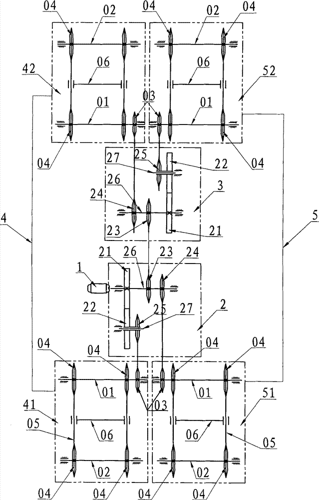
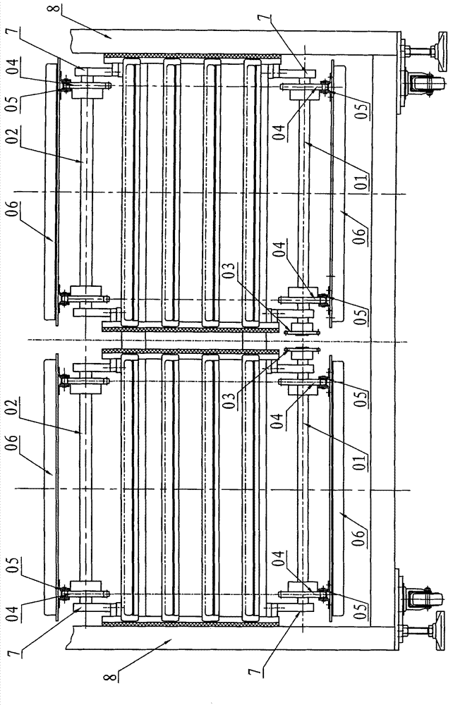
[0029] Embodiment 1: The vertical process delay curing device of the printing machine described in the present invention, such as Figure 2 to Figure 8 As shown, it includes a synchronous lifting linkage mechanism and a horizontal conveying mechanism that drive the transfer table. The synchronous lifting linkage mechanism includes a reducer 1, an outer transmission box 2, an inner transmission box 3, a synchronous lowering mechanism 4, Lifting mechanism 5, bearing seat 7 and frame 8, reducer 1 drives outer transmission box 2, outer transmission box 2 drives inner transmission box 3, and said outer transmission box 2 includes driving gear 21, driven gear 22, transmission sprocket I 23, transmission sprocket II24, transmission sprocket III25, driving shaft 26 and driven shaft 27, drive gear 21, transmission sprocket I 23 and transmission sprocket II 24 are fixedly equipped with on driving shaft 26, on driven shaft Driven gear 22 and transmission sprocket III25 are housed on 27, ...

Embodiment 2

[0032] Embodiment 2: In Embodiment 1, the reducer 1 in the synchronous lifting linkage mechanism drives the driven shaft 27 in the outer transmission box 2, and the driven gear 22 and the transmission sprocket III25 are fixedly installed on the driven shaft 27 .

[0033] There are many embodiments of the present invention. The speed reducer 1 in the synchronous lifting linkage mechanism can also drive the driving shaft 26 or the driven shaft 27 in the inner transmission box 3, and can also drive any transmission interface in the entire transmission system. Such a transmission structure, as long as the synchronous lifting linkage mechanism can ensure that the synchronous lowering mechanism and the synchronous rising mechanism turn in opposite directions and have the same rotational speed.


PUM


Abstract

The invention relates to a vertical travel increasing delayed curing device of a printing machine. The device comprises a synchronous descending and ascending linked mechanism and a horizontal conveying mechanism, wherein the synchronous descending and ascending linked mechanism comprises a speed reducer, an outer transmission box, an inner transmission box, a synchronous descending mechanism and a synchronous ascending mechanism; the inner transmission box and the outer transmission box have the same structure and are driven by the speed reducer; and the synchronous descending mechanism and the synchronous ascending mechanism have the same structure and are driven by the inner transmission box and the outer transmission box to synchronously descend and ascend, and the cooling curing travel of printing ink can be increased in the vertical direction, so that cooling curing time is prolonged, and the printing ink of a pattern printed by each printing head has been cured when transferred to the next printing head, and printing quality is improved. By a method for increasing a cooling curing path in the vertical direction, the cooling curing effect is good, the phenomenon that the printing ink is pressed, broken, extended and collapsed to block a silk screen is avoided, and the quality of the printed pattern is ensured; and the device occupies only two stations, so that the occupied area of a printing production line is reduced, and the speed of the printing production line can be improved.

Description

Technical field: [0001] The invention relates to a textile printing machine, in particular to a cooling, drying and solidifying device for printing ink in a printing unit in the printing machine. Background technique: [0002] At present, the printing machines used in the market are all traditional oval printing machines, whose structure is as follows: figure 1 As shown, it includes a transfer table, a printing head, a flash oven and a transmission mechanism for the translation of the transfer table, wherein the transfer table is used to paste the printed fabric, and the transfer table is composed The transmission mechanism drives the directional translation transmission between the printing heads to ensure that the transfer table can be positioned accurately when it is transferred to the corresponding printing heads, so as to meet the accurate printing requirements of various patterns and colors during color printing; The screen frame, scraper and scraper action mechanism,...

Claims


Application Information

Patent Timeline
Patent Type & Authority Patents(China)
IPC IPC(8): B41F23/04
Inventor 王永鑫
Owner 常州市奥伦自动化设备有限公司
Why Eureka
Try Eureka