
fan assembly

A technology of fan components and components, which is applied in the direction of liquid variable displacement machines, non-variable displacement pumps, pump devices, etc., and can solve the problems of single air flow area and discomfort

Inactive Publication Date: 2011-12-21
应辉
View PDF8 Cites 7 Cited by
  • Summary
  • Abstract
  • Description
  • Claims
  • Application Information

AI Technical Summary

Problems solved by technology

However, the air outlet direction of these two fan assemblies is fixed, and the air flow area is single when in use, and the air blows in one direction all the time, which will bring discomfort

Method used


Image

  • fan assembly
  • fan assembly
  • fan assembly

Examples


Embodiment Construction

[0022] The present invention will be described in further detail below in conjunction with the accompanying drawings.

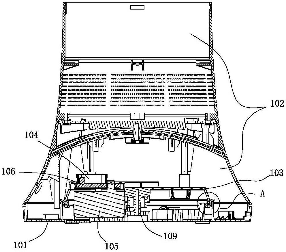
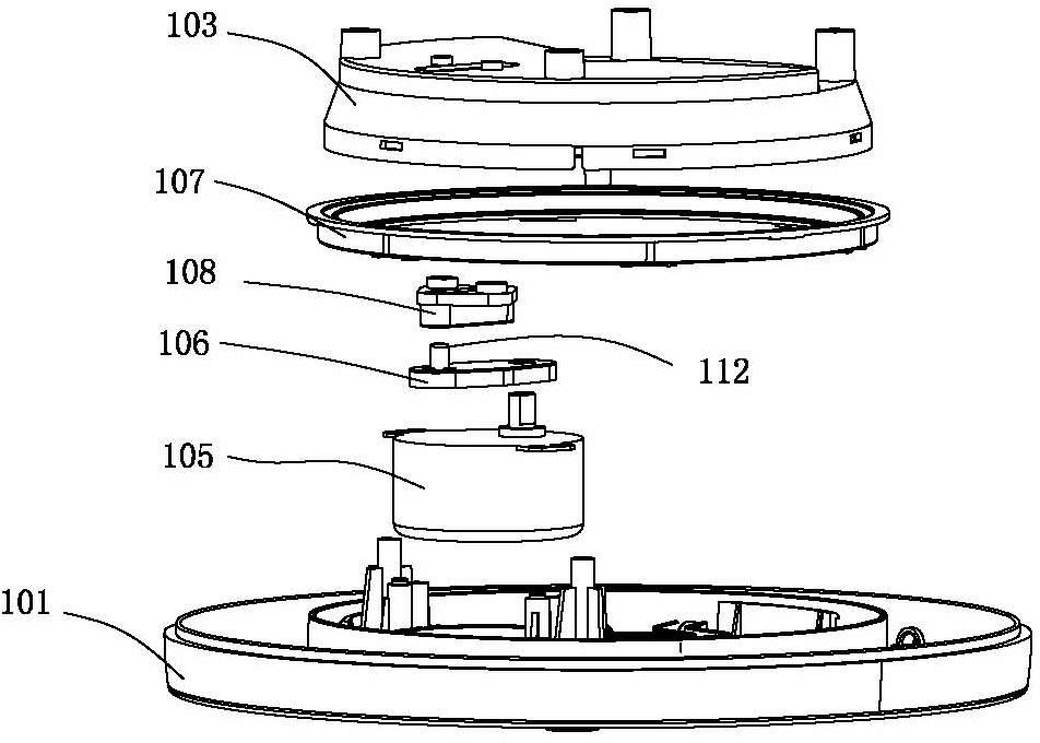
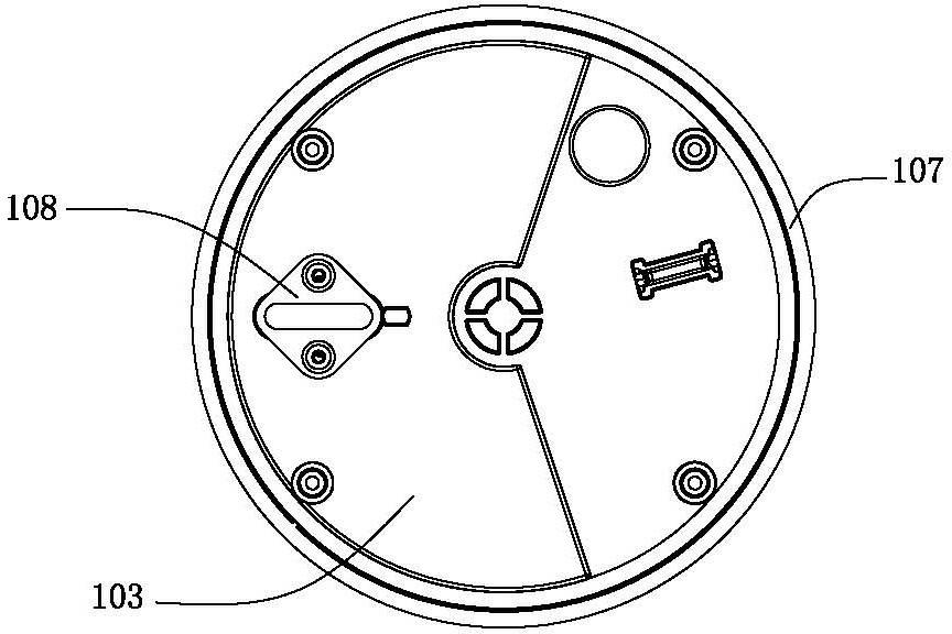
[0023] refer to Figure 1-Figure 4 , the first embodiment of the present invention is a fan assembly for generating air flow, the fan assembly includes a nozzle installed on the base, the base is provided with an impeller cover; the impeller cover has an air inlet and an air outlet, the impeller The housing is provided with an impeller and a motor for driving the impeller, the nozzle includes an internal channel for receiving airflow from the air outlet of the impeller housing and a mouth through which the airflow is ejected from the fan assembly; wherein the base further includes A base 101 and a column 102, a swing mechanism is arranged between the base 101 and the column 102; the nozzle extends around an axis to define an opening, and the air flow ejected from the mouth takes the air from Suction from the outside of the fan assembly passes through the ope...


PUM


Abstract

The present invention relates to a fan device, in particular to a bladeless fan assembly. The fan assembly includes a nozzle mounted on a base, the base further includes a base and a column, and a swing mechanism is arranged between the base and the column. The present invention provides a bladeless fan assembly whose air flow area can be automatically adjusted, and is more comfortable to use.

Description

technical field [0001] The invention relates to a fan device, in particular to a bladeless fan assembly. Background technique [0002] The usual fan is blade-type, and the blades rely on their lift angles during the rotation process to form forward wind force. The wind of this traditional fan is intermittent, and the impact of the wind pulsatingly on the human body will cause discomfort. [0003] Later, people used the principle of continuous wind and the amplification effect of the Coanda surface to produce a bladeless fan, which solved the above problems. For example, the "Fan" disclosed in the Chinese patent document CN101424279A on May 6, 2009 belongs to the bladeless fan, and the invention discloses a fan device for generating air flow. A bladeless fan assembly is provided that includes a nozzle and means for generating air flow through the nozzle. The nozzle includes an internal passage, an exhaust port for receiving airflow from the internal passage, and a Coanda s...

Claims


Application Information

Patent Timeline
Patent Type & Authority Applications(China)
IPC IPC(8): F04B41/06
CPCF04D25/10
Inventor 应辉
Owner 应辉
Learn More