
Rapid separation and integral hoisting method for pile head of cast-in-place concrete pile

An integral hoisting and concrete technology, applied in sheet pile wall, construction, infrastructure engineering and other directions, can solve the problems of high efficiency, high quality inconsistency, manpower and material resources, major damage to the main reinforcement, etc., to achieve the reduction of construction equipment and personnel, The effect of saving time and less supporting equipment

Inactive Publication Date: 2013-08-07
GANSU TIEKE CONSTR ENG CONSULTING +1
View PDF5 Cites 2 Cited by
  • Summary
  • Abstract
  • Description
  • Claims
  • Application Information

AI Technical Summary

Problems solved by technology

Due to the strong binding force of concrete on the main reinforcement of the pile head, it is necessary to peel off the main reinforcement wrapped by concrete one by one and remove the excess concrete, which consumes a lot of manpower and material resources. The labor intensity is high and the construction speed is slow, especially for the pile body. The quality and the damage of the main reinforcement of the pile body are large, which is inconsistent with the high efficiency and high quality required by the current massively developed infrastructure projects

Method used


Image

  • Rapid separation and integral hoisting method for pile head of cast-in-place concrete pile
  • Rapid separation and integral hoisting method for pile head of cast-in-place concrete pile
  • Rapid separation and integral hoisting method for pile head of cast-in-place concrete pile

Examples


Embodiment Construction

[0025] The present invention will be further described below in conjunction with specific embodiment and accompanying drawing:

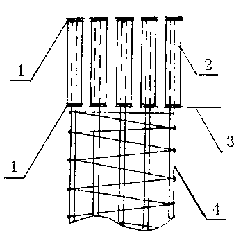
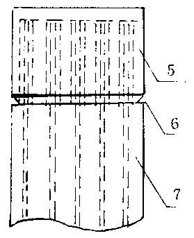
[0026] Such as figure 1 As shown, before the reinforcement cage is lowered, the elbow of the main reinforcement 4 of the reinforcement cage is not applied first (in the construction design of some cast-in-place piles, in order to strengthen the connection effect between the concrete pouring pile and the cap, the end of the main reinforcement 4 of the reinforcement cage is made into a 90° 。 Elbow), first install a plastic casing 2 (PVC casing) with a certain length, wall thickness and hardness on the top of the main reinforcement 4 of the steel cage (the pile head section needs to be chiseled), and the inner diameter is larger than the outer diameter of the main reinforcement 4 of the steel cage. The inner diameter, wall thickness and hardness of the casing 2 must meet the requirements. The length and insertion position of the plastic casing 2 must be...


PUM


Abstract

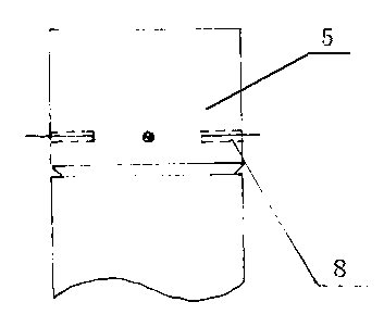
The invention discloses a rapid separation and integral hoisting method for the pile head of a cast-in-place concrete pile. Before a steel reinforcement cage is lowered down, a sleeve is firstly installed at the top end of the steel reinforcement cage on a main reinforcement with a pile head section which is required to be chiseled off; the two ends of the sleeve are plugged to prevent cement from entering the sleeve; after the strength of concrete in a pile body reaches the design requirement and the pile head is excavated, a slip is cut at the bottom end of the pile head section to be chiseled off along the annular direction of the pile head, and an annular groove is chiseled upwards to expose the sleeve; at least three bores are drilled on the annular side wall of the lower part of thepile head section to be chiseled off, reinforcement short sections are inserted into the drilled bores, and the exposed parts of the reinforcement short sections are used for tying a steel wire rope for hoisting; and hoisting can be conducted after the steel wire rope is well tied, so that the pile head section required to be chiseled off which is separated from the main reinforcement of the pilehead is integrally hoisted. Since the concrete of the pile head section to be chiseled off and the main reinforcement are not bonded with each other, when the pile head is chiseled off, the operationfor stripping the main reinforcement of the pile head off from the concrete is not required, the pile head chiseling speed is greatly accelerated, and the construction cost is reduced.

Description

technical field [0001] The invention belongs to the technical field of concrete pouring pile construction, and in particular relates to a method for treating the superfilled part of the concrete pouring pile pile head according to the standard. Background technique [0002] Due to the mature construction technology of concrete pouring piles, strong stratum adaptability and good bearing capacity, they are widely used in various foundation projects. In the construction of cast-in-situ piles, in order to ensure the quality of the pile head concrete, the constructors should exceed the set height of the pile head by 0.5-1.0m when pouring concrete according to the specification requirements (so the section is mixed with laitance and mud) , and then chisel off the excess part (called broken pile head). [0003] In order to chisel away the concrete beyond the pile head of the set cast-in-situ pile, manual chiseling or manual auxiliary small-scale machinery is still used at present....

Claims


Application Information

Patent Timeline
Patent Type & Authority Patents(China)
IPC IPC(8): E02D5/34
Inventor 刘卫东杨文辉刘鑫张化锋高永辉
Owner GANSU TIEKE CONSTR ENG CONSULTING
Learn More