
Lock structure for an electronic device

A technology of electronic devices and locks, applied in the field of anti-theft locks, can solve problems such as increased operation inconvenience, increased collection troubles, lost keys, etc.

Active Publication Date: 2012-01-11
SINOX LOCKKUNSHANCO LTD
View PDF7 Cites 7 Cited by
  • Summary
  • Abstract
  • Description
  • Claims
  • Application Information

AI Technical Summary

Problems solved by technology

Only the key lock needs to insert the key into the lock hole to control the movement of the lock catch or the opening / closing of the lock, so that the user must accurately insert the key into the lock hole, which increases the inconvenience of operation
Furthermore, after the electronic product is locked, the key must be stored and stored separately, which increases the trouble of collection, and at the same time, there is the problem of accidentally losing the key

Method used


Image

  • Lock structure for an electronic device
  • Lock structure for an electronic device
  • Lock structure for an electronic device

Examples


Embodiment Construction

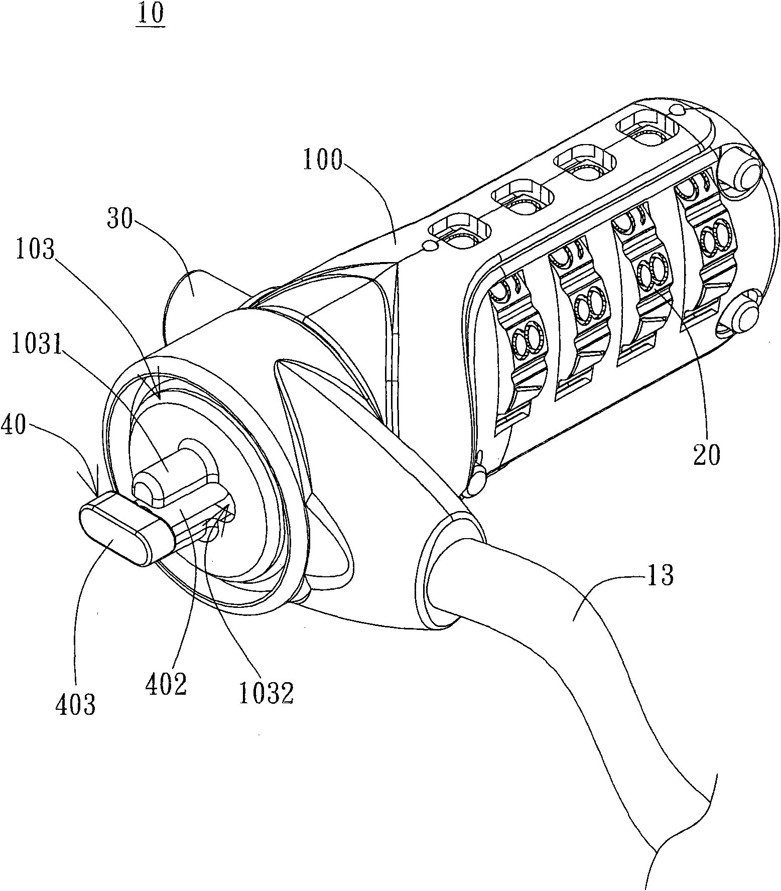
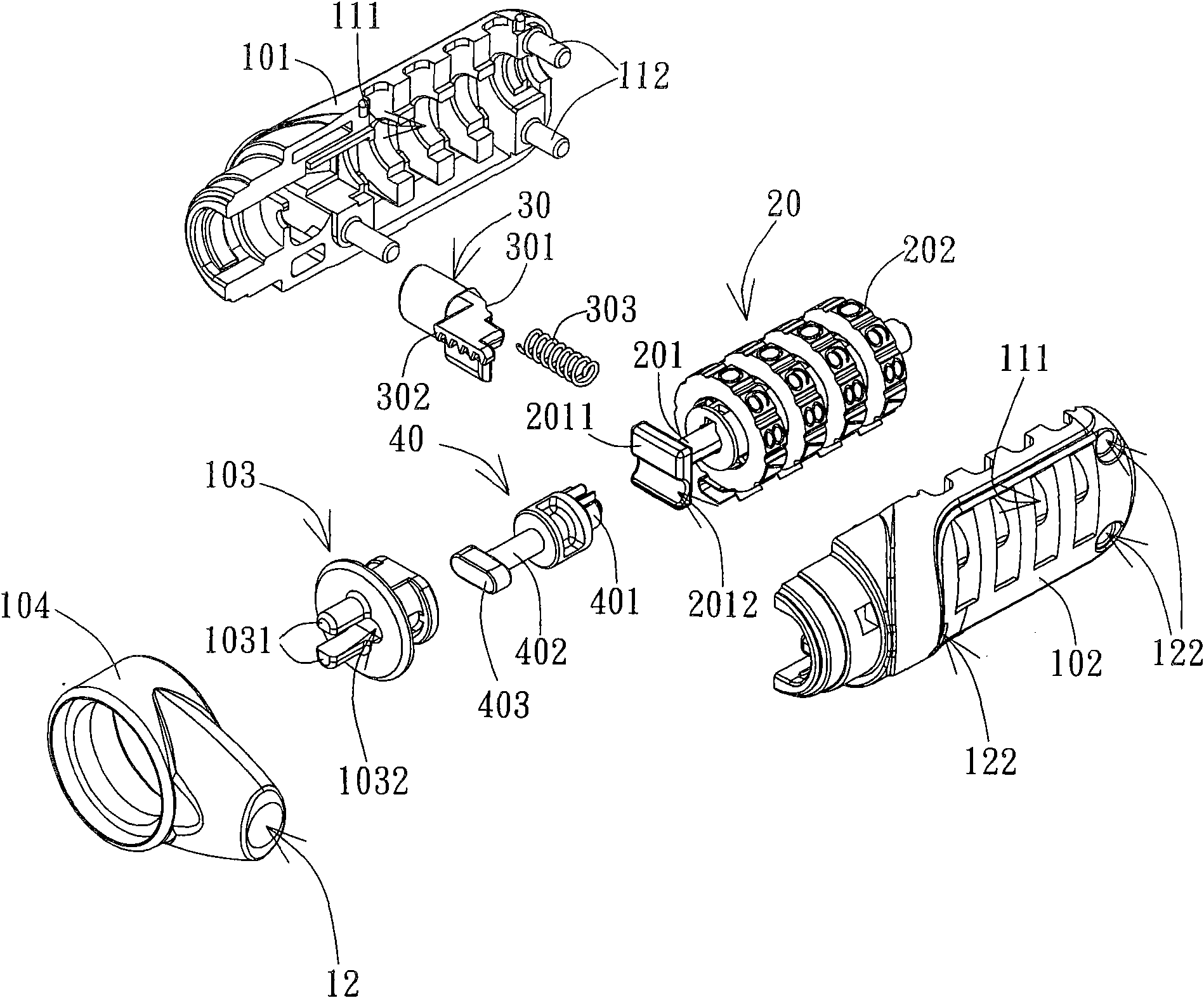
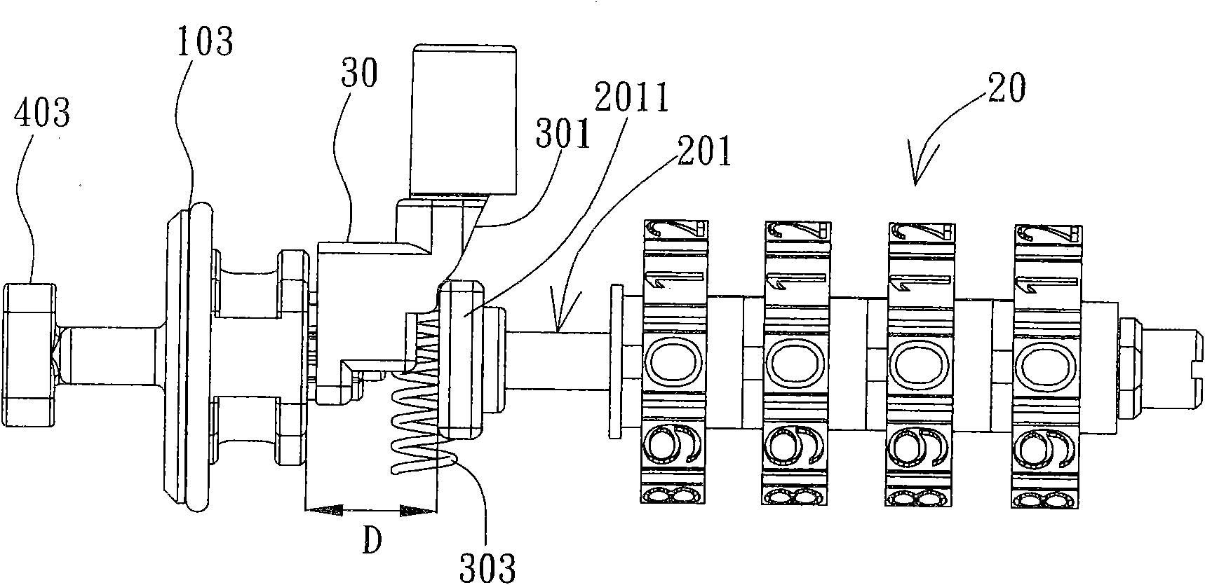
[0030] The invention provides a lock for an electronic device. In a preferred embodiment, the electronic device may include any electronic device with a keyhole, including but not limited to, for example, a notebook computer. Such as figure 1 As shown, the lock 10 includes a housing 100 , a lock body 20 , an operating device 30 and a rotary fastener 40 . The housing 100 forms at least one cavity for at least partially accommodating the lock body 20 , the operating device 30 and the rotary fastener 40 . The flexible chain 13 can be connected to the housing 100 for fixing the electronic device to a certain object, such as a table. One end of the shell 100 is protruded with a through-lock portion 1031; the through-lock portion 1031 is two columnar structures separated from each other, and the columnar structure can be, for example, cut from a cylinder into two opposite separated semi-cylindrical portions for Lateral displacement limited to one dimension. A through hole 1032 c...


PUM


Abstract

A lock structure for an electronic device is provided. The lock structure includes a rotatable fastener, a lock body, an operation device and a housing. The lock body is disposed in the housing and includes a rod member capable of moving axially. The operation device is respectively contacted against the rod member of the lock body and the rotatable fastener. When the lock body is in an unlocked state, the lock body releases the axial displacement of the rod member. At the same time, the operation device is displaced so as to drive the axial displacement of the rod member and meanwhile to drive the rotation of the rotatable fastener, resulting in the connection / detachment of the lock structure and the electronic device. When the displacement of the operation device is finished, the operation device returns to the original position, and meanwhile the rotatable fastener rotates to the original position as well so as to be clamped in a lock hole of the electronic device. When the lock body is in a locked state, the axial movement of the rod member is restricted by the lock body, so that the operation device is not operable to be displaced to rotate the rotatable fastener.

Description

technical field [0001] The invention relates to a lock, and in particular to an anti-theft lock for an electronic device. Background technique [0002] In modern life, consumer electronic products play an important role. Coupled with today's fast life style and people's demand for instant information, portable electronic products have become one of people's necessities. However, due to the high unit price and ease of realization of these products, the possibility of being stolen or stolen also increases accordingly. [0003] In order to prevent others from stealing, a lock structure is designed. For example, a notebook computer lock can be connected with the anti-theft lock hole of the electronic product with its lock, and then the movement of the lock is controlled by the key lock mechanism to complete the lock. Open / Lock purpose. Only the key lock needs to insert the key into the lock hole to control the movement of the lock catch or the opening / closing of the lock, so t...

Claims


Application Information

Patent Timeline
Patent Type & Authority Applications(China)
IPC IPC(8): E05B37/20E05B65/00
Inventor 余长江吴俊升
Owner SINOX LOCKKUNSHANCO LTD
Learn More