Eureka AIR delivers breakthrough ideas for toughest innovation challenges, trusted by R&D personnel around the world.

Photoelectric analysis method and device for gas in pipeline

A photoelectric analysis and pipeline technology, which is applied in the direction of color/spectral characteristic measurement, etc., can solve the problems of small measuring tube diameter, affecting measurement accuracy, and gas concentration can not reflect gas concentration, so as to reduce measurement error and increase measurement optical path Effect

Active Publication Date: 2013-07-10
FOCUSED PHOTONICS
View PDF3 Cites 0 Cited by
  • Summary
  • Abstract
  • Description
  • Claims
  • Application Information

AI Technical Summary

Problems solved by technology

However, the installation is often limited by the conditions of the installation section. For example, the measurement gas concentration is low, but the measurement tube diameter is too small, which limits the optical path length and makes the measuring instrument unable to meet the detection lower limit requirements; when the measurement gas concentration is high, the measurement tube diameter When it is too large, the total gas absorption is too large and enters the nonlinear region, which affects the measurement accuracy; when there is an obstacle outside the pipeline at the measurement point, the installation position of the light source and detector cannot be perpendicular to the direction of the airflow
[0010] In order to solve the above shortcomings, the pipe in the installation section of the measuring instrument is usually replaced with a pipe with a larger or smaller radius, thereby changing the measurement optical path. changes, so that the measured gas concentration cannot reflect the real gas concentration in the original pipeline

Method used


Image

  • Photoelectric analysis method and device for gas in pipeline
  • Photoelectric analysis method and device for gas in pipeline
  • Photoelectric analysis method and device for gas in pipeline

Examples


Embodiment 1

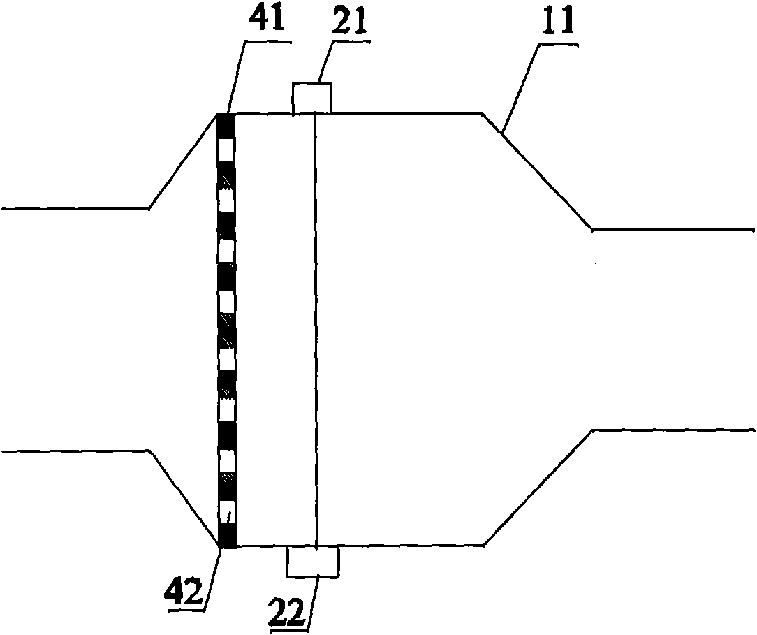
[0047] Such as figure 2 As shown, a photoelectric analysis device for the gas in the pipeline is used in the field of metallurgy to monitor the CO concentration in the pipeline. The photoelectric analysis device includes a measuring tube 11 , a flow disruptor 41 , a light source 21 , a detector 22 and an analysis unit.

[0048] The inlet and outlet of the measuring tube 11 communicate with the inside of the pipeline, so that the gas to be measured in the pipeline can flow into the measuring tube 11 by itself. The radius of the smallest covering circle of the section perpendicular to the airflow direction of the measuring tube 11 is greater than the radius of the smallest covering circle of the section of the pipe perpendicular to the airflow direction. In this embodiment, both the measuring tube 11 and the pipeline are round tubes.

[0049] Such as figure 2 As shown, the central axis of the airflow disturber 41 is parallel to the central axis of the measuring tube 11, and...

Embodiment 2

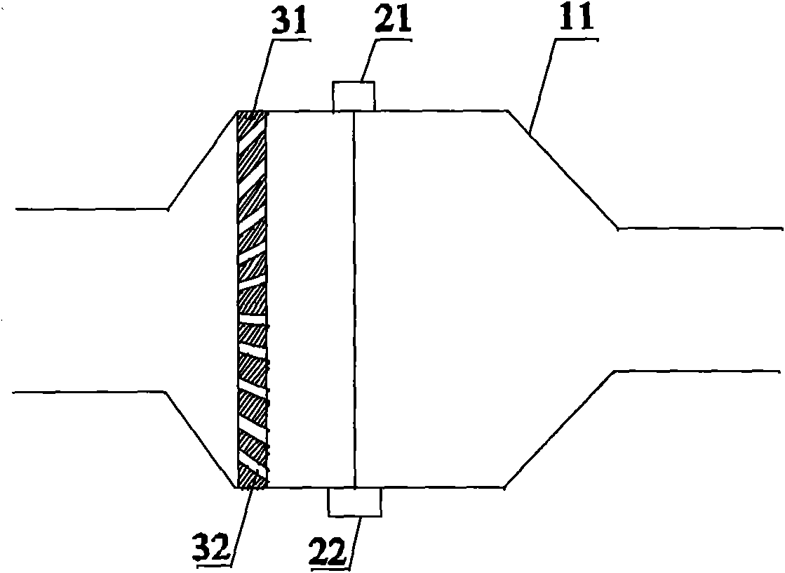
[0058] Such as image 3 As shown, a photoelectric analysis device for the gas in the pipeline is used to measure the O in the pipeline 2 Concentration, different from Example 1 is:

[0059] 1. If image 3 As shown, the included angle between the central axis of the air guide hole 32 on the airflow disturber 31 and the central axis of the measuring tube 11 is an acute angle, and the included angle gradually increases from the center to the periphery.

[0060] 2. The output wavelength of the light source 21 corresponds to O 2 the absorption spectrum lines.

[0061] Compared with the airflow disturber in Embodiment 1, the gas on the section perpendicular to the airflow direction in the upstream pipeline of the measuring tube 11 arrives at the same time, and the time difference between the light source 21 and the detector 22 on the optical path is smaller, so it can be more accurate. Accurately reflect the O in the pipeline at a certain moment 2 Concentration, better used to ...

Embodiment 3

[0067] Such as Figure 4 As shown, a photoelectric analysis device for the gas in the pipeline is used in the chemical industry to measure the CO in the pipeline 2 Concentration, different from Example 1 is:

[0068] 1. If Figure 4 As shown, the air flow disturber 51 adopts porous media.

[0069] 2. The output wavelength of the light source 21 corresponds to the CO 2 the absorption spectrum lines.

[0070] 3. If Figure 5 As shown, the cross-section of the measuring tube perpendicular to the airflow direction is a rectangle 61, and the cross-section of the pipe perpendicular to the airflow direction is a circle, but the radius R1 of the smallest covering circle of the rectangle 61 is greater than the radius of the circle R2.

[0071] This embodiment also discloses a photoelectric analysis method of gas in the pipeline, which is applied in the chemical industry to monitor the CO in the pipeline 2 Concentration, different from Example 1 is:

[0072] 1. If Figure 4 As ...


PUM


Abstract

The invention relates to a photoelectric analysis method for gas in a pipeline. The method comprises the following steps that: gas to be detected in the pipeline is introduced into a measurement pipe; an airflow perturbator is arranged in the measurement pipe; a gas guiding hole which penetrates through the airflow perturbator is formed in the airflow perturbator; light which is emitted by a light source passes through the gas to be detected on the downstream of the airflow perturbator in the measurement pipe, is absorbed by the gas to be detected, then is received by a detector and is converted into an electrical signal; and an analysis unit processes the electrical signal output by the detector so as to acquire the concentration of the gas to be detected. The invention also discloses a device for realizing the method.

Description

technical field [0001] The invention relates to the analysis of gas concentration in pipelines, in particular to a photoelectric analysis method and device for gas in pipelines. Background technique [0002] In metallurgy, petrochemical, chemical, building materials and other fields, it is necessary to monitor the gas concentration in the process pipeline and use it to guide production. [0003] As a photoelectric analysis technology, gas absorption spectroscopy has many advantages such as short response time, high measurement accuracy, and low energy consumption, and is widely used in gas monitoring. The gas absorption spectrum analysis device includes a light source, a detector and an analysis unit. The specific working method is: the light source emits measurement light, and the wavelength of the measurement light corresponds to the absorption spectrum line of the gas to be measured; the measurement light passes through the gas to be measured and is absorbed, The detecto...

Claims


Application Information

Patent Timeline
Patent Type & Authority Patents(China)
IPC IPC(8): G01N21/27G01N21/31
Inventor 陈立波李增珍
Owner FOCUSED PHOTONICS
Why Eureka
Eureka Blog
Learn More