Cuvette

A cuvette, a pair of technology, applied in the field of cuvettes, can solve the problems of reduced universality of the instrument, failure to consider the refraction utility, etc., and achieve the effect of improving sensitivity, improving sensitivity, and reducing detection limit

Pending Publication Date: 2019-03-26
安徽省环境监测中心站
View PDF6 Cites 2 Cited by
  • Summary
  • Abstract
  • Description
  • Claims
  • Application Information

AI Technical Summary

Problems solved by technology

However, this invention also has the following disadvantages: First, it fails to consider the refraction effect between the air and the liquid surface of the solution, and the uncertainty of the height of the liquid surface superimposes the refraction effect so that the position and angle of the outgoing light will change at any time; The change of the position of the optical device of the instrument puts forward higher requirements, and the instrument universality of the method is greatly reduced

Method used


Image

  • Cuvette
  • Cuvette
  • Cuvette

Examples


Embodiment 1

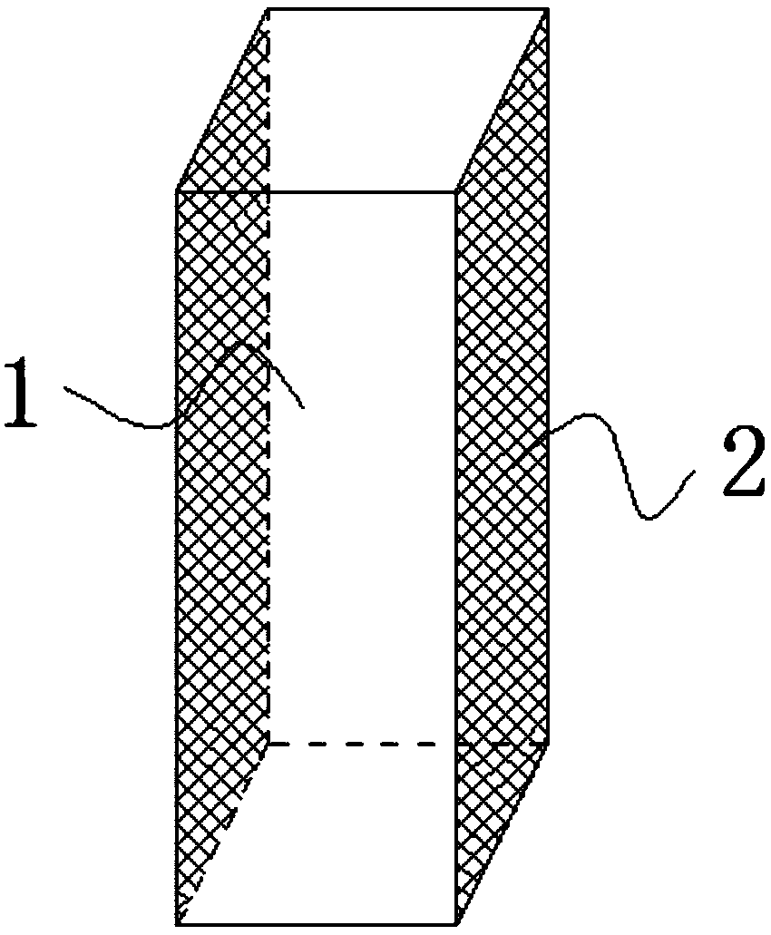
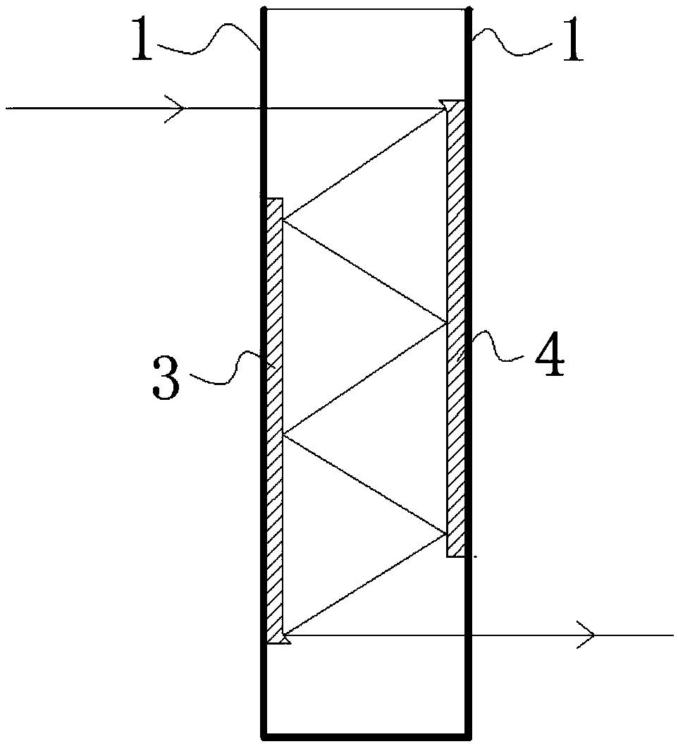
[0031] like figure 1 , 2 As shown, a cuvette has a square cylindrical structure, including a pair of parallel light-transmitting plates 1 and a pair of parallel non-light-transmitting plates 2, and the first reflective film 3 and the second reflective film 4 are respectively fixed on the On the two opposite transparent plates 1 , the first reflective film 3 and the second reflective film 4 are arranged in a staggered manner, so that light enters from the transparent plate 1 on one side and exits from the transparent plate 1 on the other side.

[0032] like figure 2 As shown, the top of the second reflective film 4 and the bottom of the first reflective film 3 in this embodiment are both in the shape of a curved arc or a broken line 5. 1 direction incident, perpendicular to the transparent plate 1 direction emission.

Embodiment 2

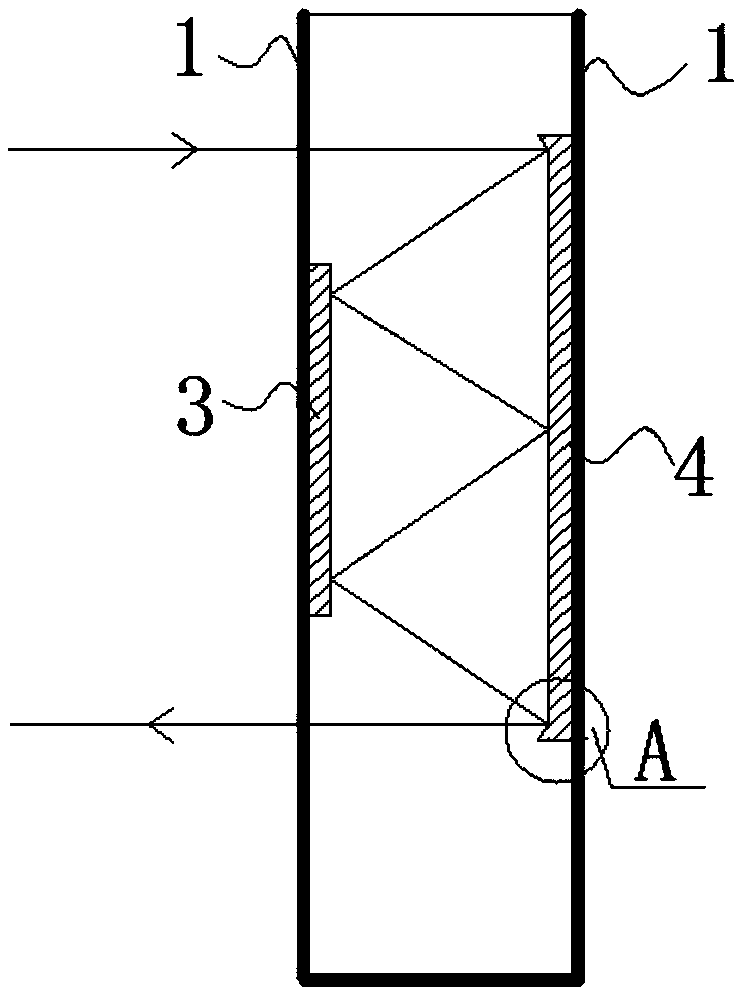
[0034] like figure 1 , 3 As shown, a cuvette has a square cylindrical structure, including a pair of parallel light-transmitting plates 1 and a pair of parallel light-transmitting plates 2, and the first reflective film 3 and the second reflective film 4 are respectively Fixed on two oppositely arranged light-transmitting plates 1, the vertical distance between the top of the first reflective film 3 and the top of the light-transmitting plate 1 is A, and the vertical distance between the bottom of the first reflecting film 3 and the bottom of the light-transmitting plate 1 is B , the vertical distance between the top of the second reflective film 4 and the top of the transparent plate 1 is a, and the vertical distance between the bottom of the second reflective film 4 and the bottom of the transparent plate 1 is b, wherein A>a, B>b.

[0035] like image 3 As shown, both sides of the second reflective film 4 are in the shape of a curved arc or a broken line 5, and the curved ...

Embodiment 3

[0037] like figure 2 As shown, a cuvette has a square cylindrical structure and includes two pairs of light-transmitting plates 1 arranged in parallel. The first reflective film 3 and the second reflective film 4 are respectively fixed on a pair of mutually parallel light-transmitting plates 1 , and the first reflective film 3 and the second reflective film 4 are mutually staggered so that light enters from one side of the light-transmitting plate 1 and the other side of the light-transmitting plate 1 emits.

[0038] In this embodiment, the top of the second reflective film 3 and the bottom of the first reflective film 4 are in the shape of a curved arc or a broken line 5, so that light can be incident along a direction perpendicular to the light-transmitting plate 1, and perpendicular to the light-transmitting plate 1 Direction shot.


PUM


Abstract

The invention belongs to the field of optical measurement and specifically relates to a cuvette. A first reflecting film and a second reflecting film are oppositely arranged on a side wall of the cuvette, wherein the first reflecting film and the second reflecting film are matched with each other and are capable of increasing optical distance of light in the cuvette through light reflection. The cuvette has the beneficial effects: 1) the first reflecting film and the second reflecting film are arranged on the side wall of the cuvette, the measuring optical distance is effectively increased through repeated reflection when light emits into the cuvette, and the detection limit of the present method is greatly reduced and sensitivity is promoted under the condition of no change on appearanceand size of the cuvette; 2) arc-shaped or broken line structures are arranged on the two sides of the second reflecting film or are respectively arranged on the first reflecting film and the second reflecting film, so that the directions of incident light and emergent light are both vertical to the side wall of the cuvette, and the present spectrophotometer can be matched with the cuvette throughslight adjustment for light path.

Description

technical field [0001] The invention belongs to the field of optical measurement, and in particular relates to a cuvette. Background technique [0002] Spectrophotometric analysis is based on the Lambert-Beer law for quantitative analysis and is a common instrumental analysis method. Due to the low cost of equipment and relatively simple operation, spectrophotometric analysis is widely used in detection activities in the fields of environment, sanitation, and water conservancy. [0003] The physical meaning of the Lambert-Beer law is that when a beam of parallel monochromatic light passes through a uniform non-scattering light-absorbing material vertically, its absorbance A is proportional to the concentration c of the light-absorbing material and the thickness b (optical path) of the absorbing layer. In actual measurement activities, the cuvette is an important photometric measurement component, and its optical path size has an important impact on the sensitivity and detec...

Claims


Application Information

Patent Timeline
Patent Type & Authority Applications(China)
IPC IPC(8): G01N21/03G01N21/17
CPCG01N21/03G01N21/17
Inventor 史绵红
Owner 安徽省环境监测中心站
Why Eureka
Try Eureka