Vacuum cleaner soft pipe component and vacuum cleaner

A technology for vacuum cleaners and hose assemblies, which is applied in the direction of vacuum cleaners, suction hoses, household appliances, etc., and can solve problems such as conduction state failure

Active Publication Date: 2012-02-01
TOSHIBA LIFESTYLE PROD & SERVICES CORP
View PDF5 Cites 5 Cited by
  • Summary
  • Abstract
  • Description
  • Claims
  • Application Information

AI Technical Summary

Problems solved by technology

An increase in the gap between the hole forming portion of the hand tube and the rotary tube may separate the electrode ring wound around the outer peripheral surface of the rotary tube from the contacts provided on the hand tube, which may cause failure of the conduction state therebetween

Method used


Image

  • Vacuum cleaner soft pipe component and vacuum cleaner
  • Vacuum cleaner soft pipe component and vacuum cleaner
  • Vacuum cleaner soft pipe component and vacuum cleaner

Examples


Embodiment Construction

[0022] The following will refer to Figure 1-6 Embodiments of a vacuum cleaner hose assembly and a vacuum cleaner according to the present invention are described. It is to be noted that the terms "up", "down", "right", "left" and similar terms denoting directions are used in this specification with reference to the state shown in the drawings, or with figure 1 Use the actual usable state of the vacuum cleaner.

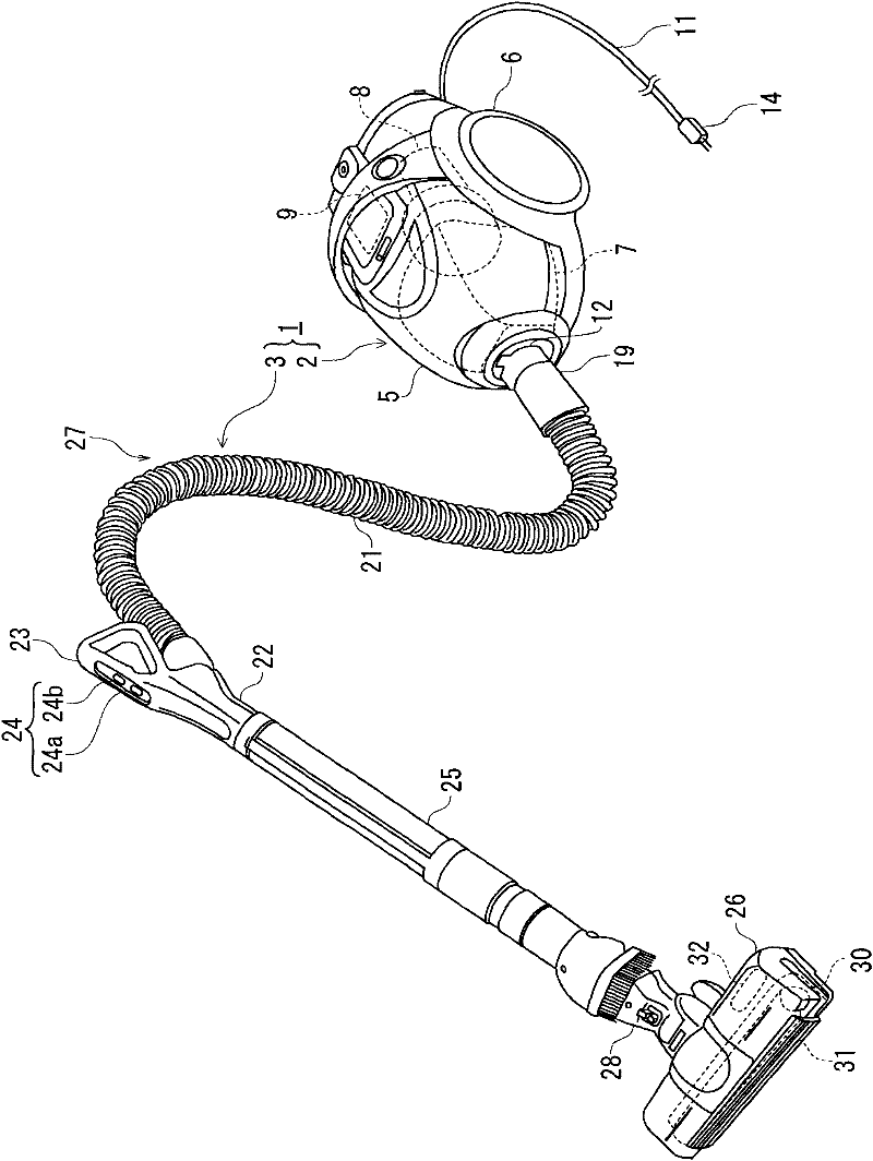
[0023] refer to figure 1 , which shows a perspective view of a vacuum cleaner according to one embodiment, the vacuum cleaner 1 being a so-called canister-type vacuum cleaner.

[0024] The vacuum cleaner 1 includes a vacuum cleaner body 2 freely movable on a cleaning surface (surface to be cleaned) and a pipe unit 3 connected to the vacuum cleaner body 2 in a detachable manner.

[0025] The vacuum cleaner body 2 includes a body case 5, a pair of wheels 6 pivotably supported on both sides of the body case 5, a dust separation / collection unit 7 detachably mounted to ...


PUM


Abstract

The invention provides a vacuum cleaner soft pipe component, comprising: a soft pipe; a manually-operated pipe communicated with the soft pipe; a holding member connected with the manually-operated pipe, and an operation unit installed on the manually-operated pipe. The soft pipe is provided with a plurality of leads in a transmission connection between the two ends. The manually-operated pipe comprises: a cylindrical rotating pipe section disposed at one end side of the soft pipe; an electrode collar group comprising a plurality of electrode collars arranged along the central line of the rotating pipe section, winded at the periphery, and electrically connected with each lead; an outer cover member covering the electrode collar group and pivotably supporting the rotating pipe around the central line of the rotating pipe section; leads going through the manually-operated pipe and a contact group comprising a plurality of contacts electrically connected to the operation unit and the electrode collars. The contact group comprises a first contact group comprising a plurality of contacts closer to one end part of the electrode collar group and in a same-phase-arrangement seen from the circumferential direction of the rotating pipe section, and a second contact group comprising a plurality of contacts closer to the other end part of the electrode collar group and in a different-phase-arrangement from the first contact group seen from the circumferential direction of the rotating pipe section.

Description

technical field [0001] The invention relates to a hose assembly of a vacuum cleaner and a vacuum cleaner. Background technique [0002] A canister-type vacuum cleaner includes a vacuum cleaner body, an electric fan installed in the vacuum cleaner body, a vacuum cleaner hose assembly that can be detachably (connectable and detachable) connected to the vacuum cleaner body, The extension pipe is detachably connected with the hose assembly of the vacuum cleaner, and the suction body is detachably connected with the front end of the extension pipe. [0003] A conventional vacuum cleaner with such a configuration drives an electric fan to generate negative pressure, which is sequentially transmitted from the vacuum cleaner body to the vacuum cleaner hose assembly, the extension pipe, and the suction body to pass through the suction port opened in the suction body. to vacuum the dust. [0004] The vacuum cleaner hose assembly is flexible and allows relative movement of the nozzle...

Claims


Application Information

Patent Timeline
IPC IPC(8): A47L9/24
CPCA47L5/362A47L9/246A47L9/248A47L9/327
Inventor 町田幸雄大下悟
Owner TOSHIBA LIFESTYLE PROD & SERVICES CORP
Why Eureka
Try Eureka