
Connector device, method of manufacturing the same, and battery pack using the same

a technology of connecting device and battery pack, which is applied in the manufacture of final products, cell components, and coupling device connections, etc., can solve problems such as the problem of conventional connector devices b>101/b>

Inactive Publication Date: 2008-10-30
SANYO ELECTRIC CO LTD +1
View PDF8 Cites 2 Cited by
  • Summary
  • Abstract
  • Description
  • Claims
  • Application Information

AI Technical Summary

Benefits of technology

[0014]A connector device in accordance with the present invention includes a circuit board, a connector body, and a sealing member. The connector body is attached to a main surface of the circuit board, and has a connection terminal electrically connected to a prescribed terminal on the circuit board and a housing holding and covering the connection terminal. The sealing member fills a gap between the housing and the circuit board.
[0015]According to this configuration, the gap between the housing and the circuit board is filled with the sealing member. Thereby, when the connector device is sealed with a mold resin, the mold resin is prevented from entering into the connector body. As a result, failure of conduction between the connection terminal provided inside the connector body and external equipment such as a mobile phone body can be prevented.
[0024]According to this method, the sealing member is applied to fill the gap between the connector body and the circuit board, and then cured. Thereby, when the connector device is sealed with a mold resin, the mold resin is prevented from entering into the connector body. As a result, failure of conduction between the connection terminal provided inside the connector body and external equipment such as a mobile phone body can be prevented.
[0032]According to this configuration, the gap between the housing and the circuit board is filled with the sealing member. Thereby, when the connector body, the circuit board, and the battery pack body are sealed with the mold resin, the mold resin is prevented from entering into the connector body. As a result, failure of conduction between the connection terminal provided inside the connector body and external equipment such as a mobile phone body and interruption of electric power supply can be prevented.

Problems solved by technology

However, conventional connector device 101 has a problem as described below.

Method used


Image

  • Connector device, method of manufacturing the same, and battery pack using the same
  • Connector device, method of manufacturing the same, and battery pack using the same
  • Connector device, method of manufacturing the same, and battery pack using the same

Examples


first embodiment

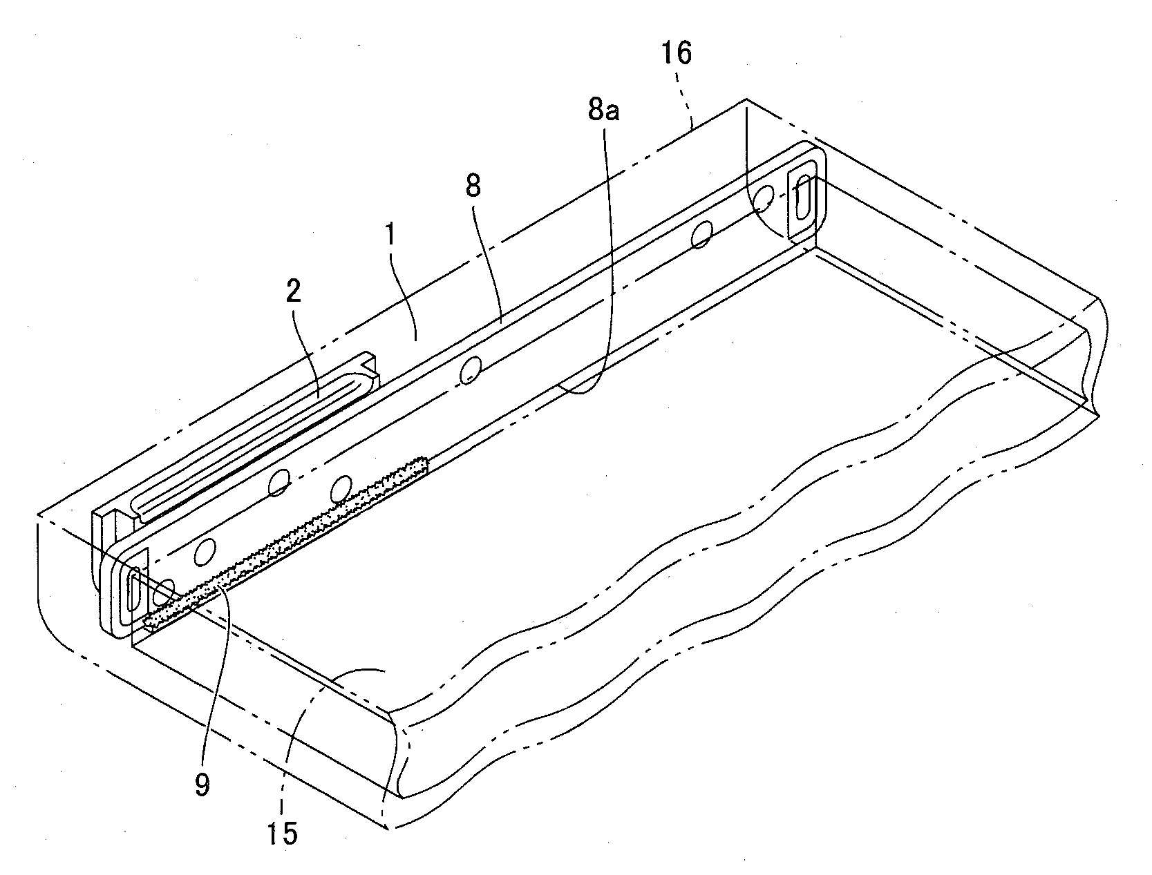
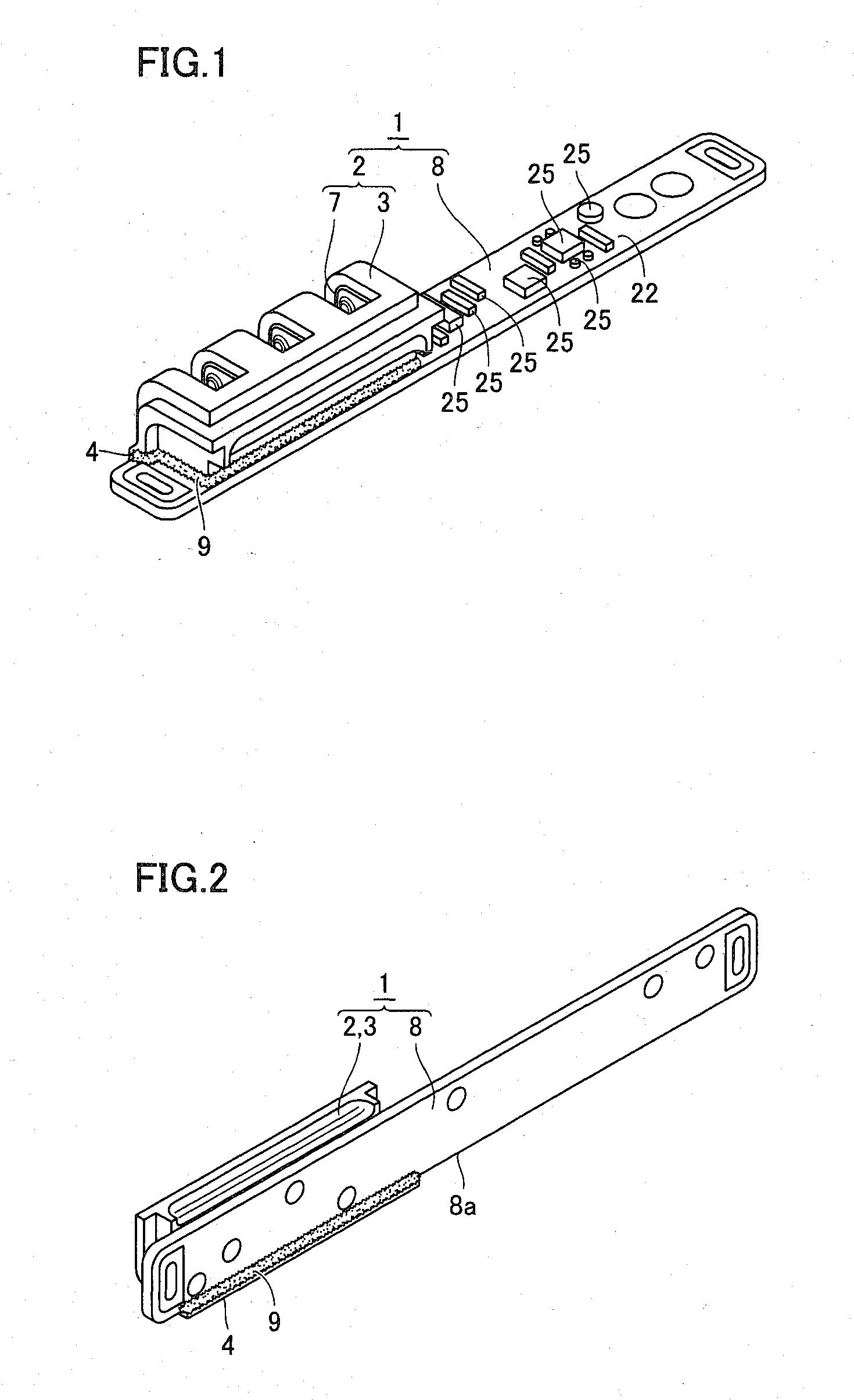
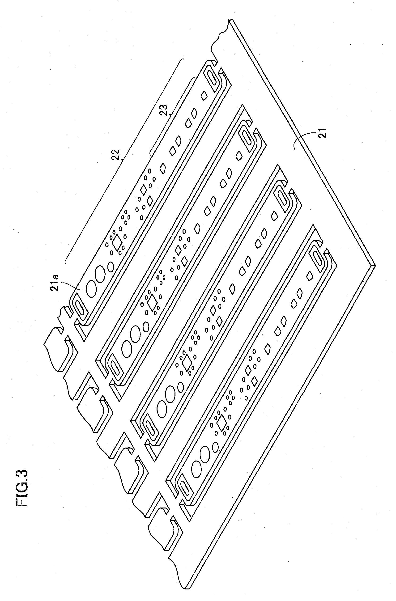
[0070]As a connector device in accordance with a first embodiment of the present invention, a connector device used in a battery pack of a mobile phone will be described. As shown in FIGS. 1 and 2, a connector device 1 includes a circuit board 8 and a connector body 2, and connector body 2 includes a housing 3 and a connection terminal 7 provided inside housing 3. Connection terminal 7 is connected to a land 23 (see FIG. 7) formed on circuit board 8.

[0071]Housing 3 is also provided with a board end surface facing portion 4 facing an end surface 8a of circuit board 8 to align connector body 2 with circuit board 8. A prescribed circuit pattern 22 is formed on a surface of circuit board 8, and a prescribed electronic component 25 is mounted based on circuit pattern 22.

[0072]In connector device 1, a silicon resin 9 is applied to fill a gap between connector body 2 and circuit board 8. As described later, when connector device 1 and a battery pack body are sealed with a mold resin, the a...

second embodiment

[0085]A connector device manufactured in less steps and a method of manufacturing the same will be described herein. As shown in FIG. 24, in connector body 2 of the connector device, a partition plate 5 provided inside housing 3 is used to introduce the applied silicon resin into the gap between board end surface facing portion 4 and the end surface of the circuit board. For that purpose, a plurality of concave portions 6 are provided at prescribed positions of housing 3.

[0086]Two partition plates 5 extend from a side on which board end surface facing portion 4 is formed to an opposite side, and have a function of each holding connection terminal 7 provided inside housing 3 and electrically insulating connection terminals 7 from each other. Two concave portions 6 are formed at a portion where each partition plate 5 is connected to an outer wall of housing 3. In the lower end portion of the outer wall of housing 3, one concave portion 6 is formed on one of two sides sandwiching parti...


PUM

PropertyMeasurementUnit
viscosityaaaaaaaaaa
thicknessaaaaaaaaaa
viscosityaaaaaaaaaa

Abstract

A connector device includes a circuit board and a connector body, and the connector body includes a housing and a connection terminal provided inside the housing. A silicon resin is applied to fill a gap between the connector body and the circuit board. The application of the silicon resin can prevent a mold resin used to seal the connector device and a battery pack body from entering from the gap into the housing. Thereby, a connector device reliably establishing conduction and a battery pack applying such a connector device can be obtained.

Description

BACKGROUND OF THE INVENTION[0001]1. Field of the Invention[0002]The present invention relates to a connector device, a method of manufacturing the same, and a battery pack using the same. In particular, the present invention relates to a connector device finally sealed with a mold resin, a method of manufacturing such a connector device, and a battery pack applying such a connector device.[0003]2. Description of the Background Art[0004]Conventionally, for example, in order to connect a battery pack of a mobile phone to a body of the phone, a connector device is used in the battery pack. The connector device includes a prescribed circuit board and a connector body fixed to the circuit board. The connector device is integrated with a battery pack body. When a terminal of the phone body is inserted into the connector body, electric power in the battery pack is supplied to the mobile phone. As an example of such a connector device, there is a connector device sealed integrally with a ba...

Claims


Application Information

Patent Timeline
Patent Type & Authority Applications(United States)
IPC IPC(8): H02J7/00
CPCH05K3/305H05K3/3421Y10T29/49002H05K2201/10446H05K2201/0162Y02P70/50H01R12/71
Inventor OKANO, FUMITAKA
Owner SANYO ELECTRIC CO LTD
Learn More