Tether for spacecraft reaction control system

Pending Publication Date: 2015-03-19
DULA ARTHUR M
View PDF7 Cites 44 Cited by
  • Summary
  • Abstract
  • Description
  • Claims
  • Application Information

AI Technical Summary

Benefits of technology

[0021]In accordance with an embodiment, the tether can be made of a heat resistant material with conductive properties making it suitable to function as an antenna. The unexposed end of the tether can be integrated with the spacecraft's radio communications system. The entire length of tether c

Problems solved by technology

There are difficulties that are inherent aspects of atmospheric entry caused by high velocity transit through an atmosphere.
These problems include high temperatures generated by friction between the entry system and the atmosphere while the atmospheric entry system is traveling through the atmosphere at high velocities, high acceleration loads experienced by the reentry system and its payload due to rapid changes in the system's velocity, and difficulty of controlling the flight path as the system descends through an atmosphere due to several causes including poor aerodynamics, high velocities, and the requirement of fast reacting guidance methods.
However, entering and traversing an atmosphere ballistically is relatively uncontrolled and can be physically damaging to the object entering the atmosphere, its payload, or to the celestial body.
Deceleration is one obstacle in atmospheric re-entry.
Aerobraking, however, presents another obstacle.
Additionally, a spacecraft's speed and the resulting collisions with molecules in the atmosphere break up neutral atoms and molecules into electrons and ions.
At higher temperatures the collisions are so violent that the electrons are knocked clear of the nucleus.
Re-entry vehicles all generate plasmas due to shock and boundary layer heating, Radio waves cannot penetrate the high

Method used


Image

  • Tether for spacecraft reaction control system
  • Tether for spacecraft reaction control system
  • Tether for spacecraft reaction control system

Examples


Embodiment Construction

[0137]In the following description, for purposes of explanation, numerous specific details are set forth in order to provide a thorough understanding of the present invention. It will be apparent, however, that the present invention may be practiced without these specific details. In other instances, well-known structures and devices are shown in block diagram form to avoid unnecessarily obscuring the present invention.

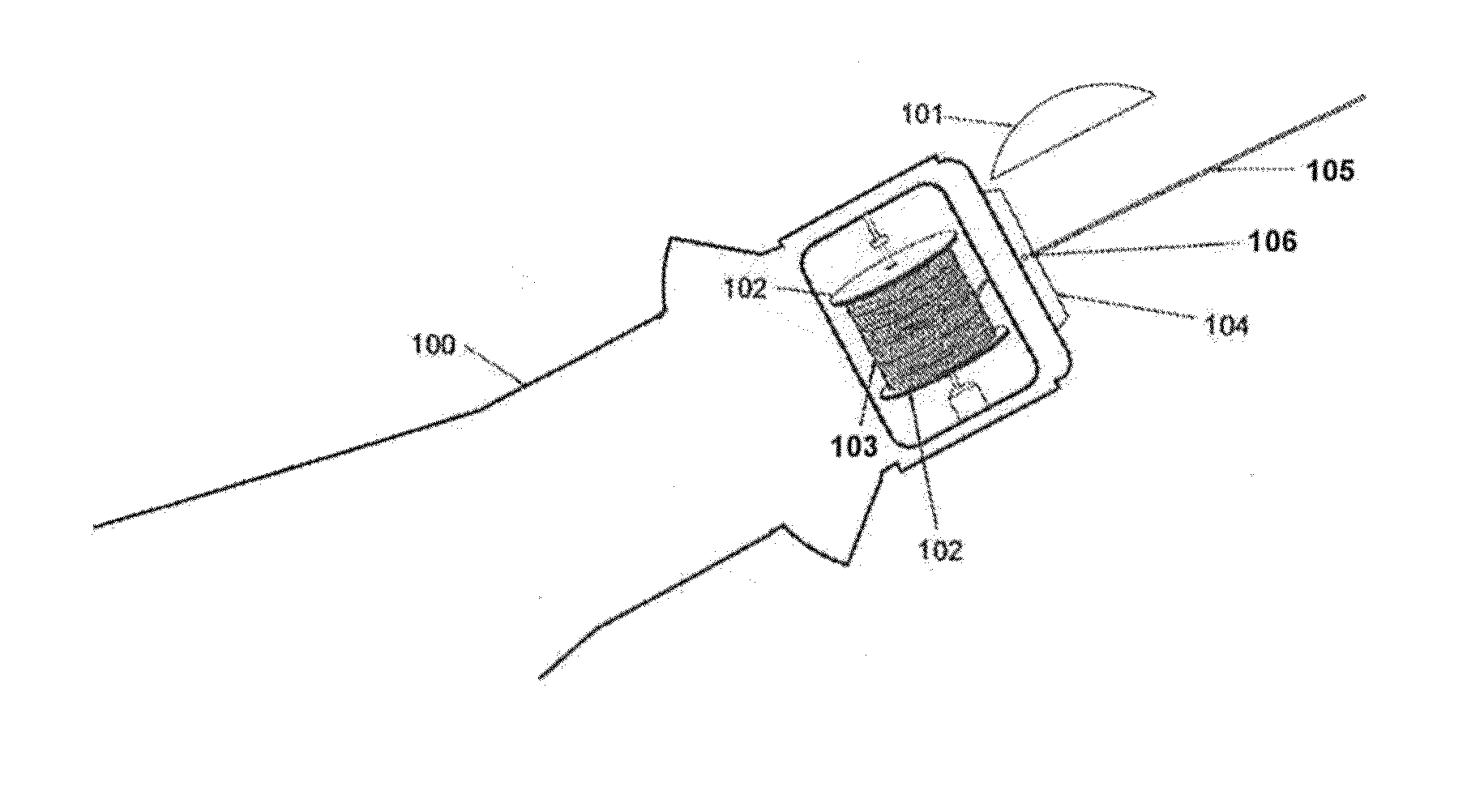
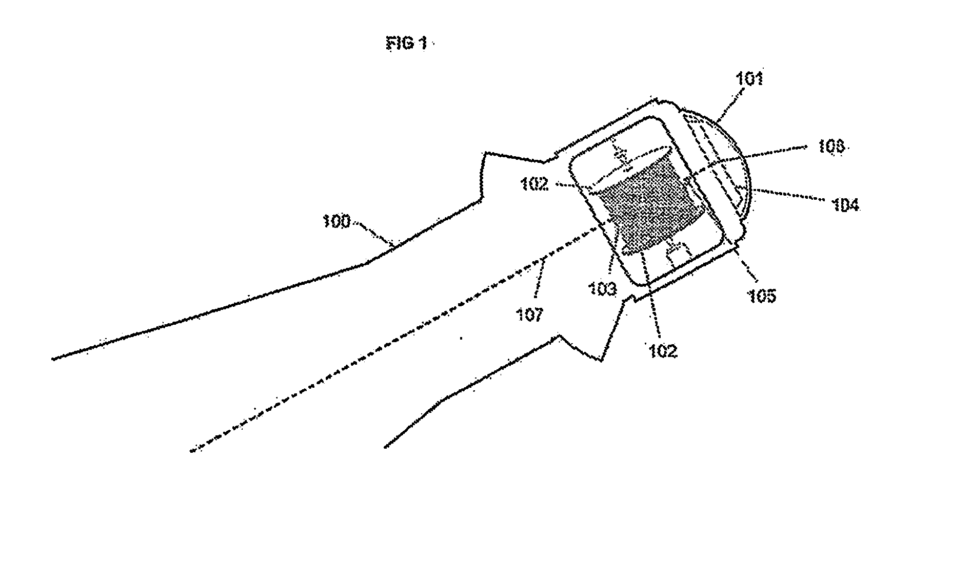
[0138]FIG. 1 illustrates a cut-away side-view of a forward section of a space capsule 100 prior to the re-entry phase, showing a tether-based RCS system comprising a control apparatus 104 and a reel 102 for holding a length of tether 103, in accordance with an embodiment. Prior to re-entry, the opening at the end of the forward section of the capsule is covered by a lid 101 for keeping an initial length of unreeled tether 105 confined within the capsule. The unreeled tether 105 is the portion of tether held by the reel 102 that is threaded through a “center hole”106 o...


PUM


Abstract

A spacecraft reaction control system comprising: a spacecraft having a center of mass; a length of tether extending from said spacecraft and offset from said spacecraft's center of mass and means for controllably changing said extension of said offset such that a variable force is exerted upon said spacecraft by said tether, said force being offset from said center of mass.

Description

CROSS-REFERENCE TO RELATED APPLICATIONS[0001]This application is a continuation in part of and claims the benefit of U.S. application Ser. No. 14 / 025,822 filed on Sep. 13, 2013, which application claims the benefit of Patent Cooperation Treaty application number US2012 / 028841 filed Mar. 12, 2012 and U.S. provisional application No. 61 / 801,092 filed Mar. 15, 2013, which applications are hereby incorporated by reference.STATEMENT RELATED TO FEDERALLY SPONSORED RESEARCH OR DEVELOPMENT[0002]Not ApplicableFIELD OF THE INVENTION[0003]The present invention pertains generally to safely return spacecrafts and space vehicles to earth's surface. The term “returnable” refers to the ability of spacecraft to leave and later reenter planetary atmospheres and reach the planet's surface intact and safe. More specifically, the invention pertains to control systems and methods of control for returnable space vehicles re-entering planetary atmosphere.BACKGROUND OF THE INVENTION[0004]Atmospheric re-entr...

Claims


Application Information

Patent Timeline
IPC IPC(8): B64G1/64B64G1/26B64G1/24
CPCB64G1/648B64G1/26B64G1/24B64G1/12B64G1/14B64G1/52B64G1/58B64G1/62B64G1/244B64G1/2227B64G1/525
Inventor DULA, ARTHUR M.
Owner DULA ARTHUR M
Why Eureka
Try Eureka