

Acoustic emission sensing in powder bed additive manufacturing
- Summary
- Abstract
- Description
- Claims
- Application Information
AI Technical Summary
Benefits of technology
Problems solved by technology
Method used
Image

Examples
Embodiment Construction
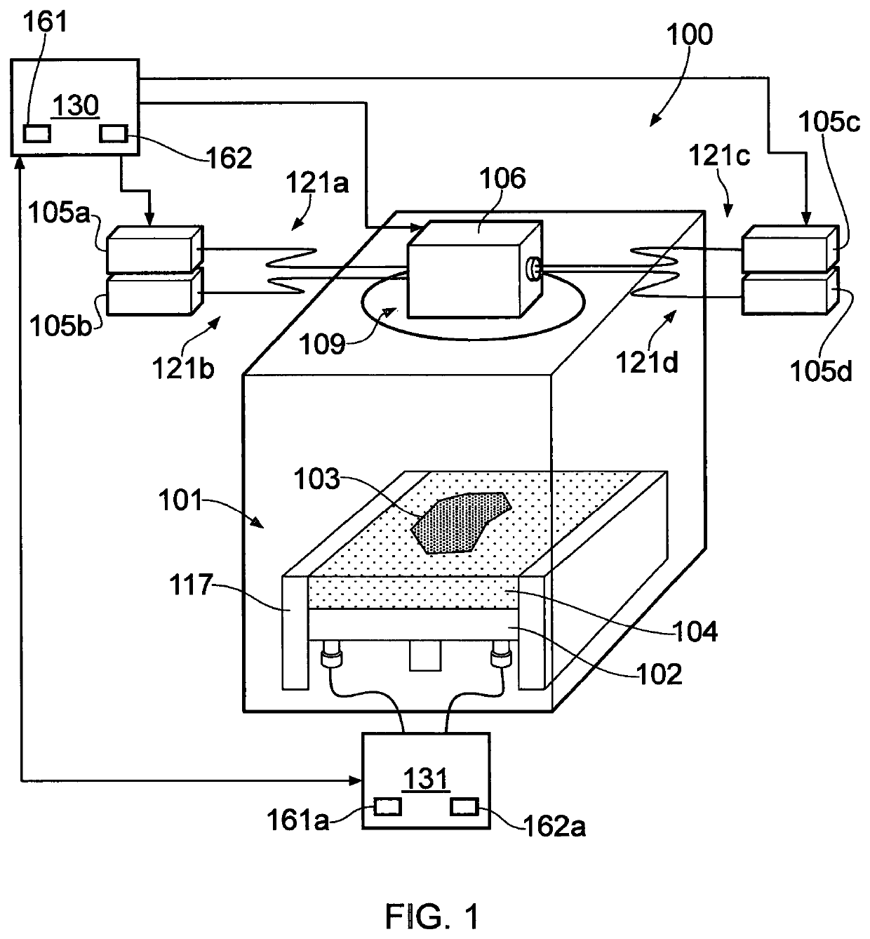
[0048]Referring to FIG. 1, an additive manufacturing apparatus 100 according to an embodiment of the invention comprises a build chamber 101 having therein a build sleeve 117 and a build platform 102 lowerable in the build sleeve 117 under the control of a drive (not shown). The build platform 102 supports a powder bed 104 and workpiece 103 as the workpiece is built by selective laser melting of the powder. During additive manufacturing, the platform 102 is lowered within the build sleeve 117 under the control of the drive as successive layers of the workpiece 103 are formed through the selective solidification of powder.
[0049]Layers of powder 104 are formed as the workpiece 103 is built by dispensing apparatus and a wiper (not shown). For example, the dispensing apparatus may be apparatus as described in WO2010 / 007396. A position of a lower edge of the wiper defines a working plane at which powder is consolidated.
[0050]A plurality of laser modules 105a, 105b, 105c and 105d generate...
PUM
| Property | Measurement | Unit |
|---|---|---|
| Proximity effect | aaaaa | aaaaa |
Abstract
Description
Claims
Application Information