
Handrail for staircase or ramp

Active Publication Date: 2012-01-12
BISHOP PAUL +1
View PDF14 Cites 2 Cited by
  • Summary
  • Abstract
  • Description
  • Claims
  • Application Information

AI Technical Summary

Benefits of technology

[0004]In one embodiment, the present invention is a riser barrier for a handrail of a staircase or ramp with the handrail being an elongated cylinder. The riser barrier includes an extender portion and a riser portion. The extender portion has a length between a proximal end and a distal end, where the proximal end is fastened to the elongated cylinder and the length being sufficient to hold the riser portion a certain horizontal distance away from the elongated cylinder. The riser portion has a length that extends vertically above the elongated cylinder so as to deter sliding on the cylinder.
[0005]In another embodiment, the present invention is a riser barrier for a handrail of a staircase or ramp with the handrail being an elongated bar. The riser barrier includes an extender portion and a riser portion. The extender portion has a length between a proximal end and a distal end, where the proximal end is fastened to the elongated bar, and the length is sufficient to hold the riser portion a certain horizontal distance away from the elongated bar. The riser portion has a length that extends vertically above the elongated bar so as to deter sliding on the bar.
[0006]In yet another embodiment, the present invention is an improved handrail for a staircase or ramp. The handrail includes an elongated member and a riser barrier. The elongated member, such as a cylinder or a bar, spans the length of the staircase or ramp. The riser barrier includes an extender portion and a riser portion. The extender portion has a length between a proximal end and a distal end with the proximal end being fastened to the elongated member and the length being sufficient to hold the riser portion a certain horizontal distance away from the elongated member. The riser portion has a length that extends vertically above the elongated member or bar so as to deter sliding on the elongated member.

Problems solved by technology

However, handrails have the unintended consequence of providing a convenient track for skateboarders.

Method used


Image

  • Handrail for staircase or ramp
  • Handrail for staircase or ramp
  • Handrail for staircase or ramp

Examples


embodiment 200

[0020]The embodiment 200 in FIG. 4A and FIG. 4B includes an elongated cylinder 110 and an arcuate riser barrier 210 with a proximal end 220 and a distal end 224. The proximal end 220 is adapted for affixation to the bottom of the elongated cylinder 110 by conforming its curvature approximately to the curvature at the bottom of the elongated cylinder. The proximal end 220 is affixed to the elongated cylinder 110 by means of tack welds 222 at points on either side of the cylinder 110 nearest to the proximal end 220 of the barrier 210. The arcuate riser barrier 210 extends laterally and rises vertically so that the distal end 224 is spaced horizontally away from the elongated cylinder 110 by dimension “d”, and vertically away by dimension “e”. In one version, dimension “d” is approximately 1½ inches and dimension “e” is approximately 3 inches. As the arcuate riser barrier 210 rises from its proximal end 220 to its distal end, the riser barrier widens and then narrows. The arc-shaped ar...

embodiment 300

[0021]The embodiment 300 in FIGS. 5A and 5B includes an elongated cylinder 110, and a riser barrier having extender portion 320 and riser portion 310. The extender portion 320 is curved downward between the proximal end 330 and the distal end 340 and holds the elongated cylinder 110 away horizontally from the riser portion 310 by dimension “k” and vertically away by dimension “p”, where, in one embodiment, dimension “k” is about 1½ inches and dimension “p” is about 1½ inches. The horizontal separation between the riser portion 310 and cylinder 110 permits the user to slide his / her hand along the cylinder 110 without interference, the downward curve of the extender portion 320 giving added room for the user's hand. The length of the riser portion 310 deters the skateboarder from sliding on the rail. As shown in the figures, the riser portion 310 has a thickness given by dimension “j”, which in one version is about ½ inch and a width given by dimension “n”, which in one version is abo...

embodiment 400

[0022]The embodiment 400 in FIGS. 6A and 6B includes an elongated bar 112 and a riser barrier having extender portion 320 and riser portion 310. The elongated bar 112 is generally rectangular or square in cross-section and may be hollow (shown) or solid. The extender portion 320 of the riser barrier is curved downward between the proximal end 332 and the distal end 340 and holds the elongated bar 112 away horizontally from the riser portion 310 by dimension “k” and vertically away by dimension “p”, where, in one embodiment, dimension “k” is about 1½ inches and dimension “p” is about 1½ inches. The horizontal separation between the riser portion 310 and bar 112 permits the user to slide his / her hand along the bar 112 without interference, the downward curve of the extender portion 320 giving added room for the user's hand. The length of the riser portion 310 deters the skateboarder from sliding on the rail. As shown in the figures, the riser portion 310 has a thickness given by dimen...


PUM


Abstract

An improved handrail for a staircase or ramp. In one embodiment, the handrail includes an elongated member such as a cylinder or bar that spans the length of the staircase or ramp and a riser barrier. The riser barrier has an extender portion and a riser portion. The extender portion of the riser barrier keeps the elongated member a sufficient distance horizontally from the riser portion that a person can slide his or her hand on the rail without interference. The riser portion projects vertically a sufficient distance above the elongated member to deter sliding down the elongated member. Thus, sliding on the member is deterred, while the function of the cylinder as a handrail is preserved.

Description

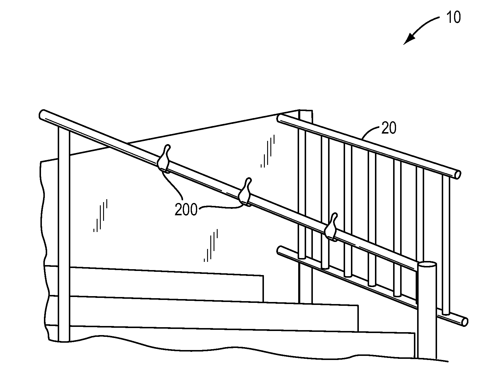
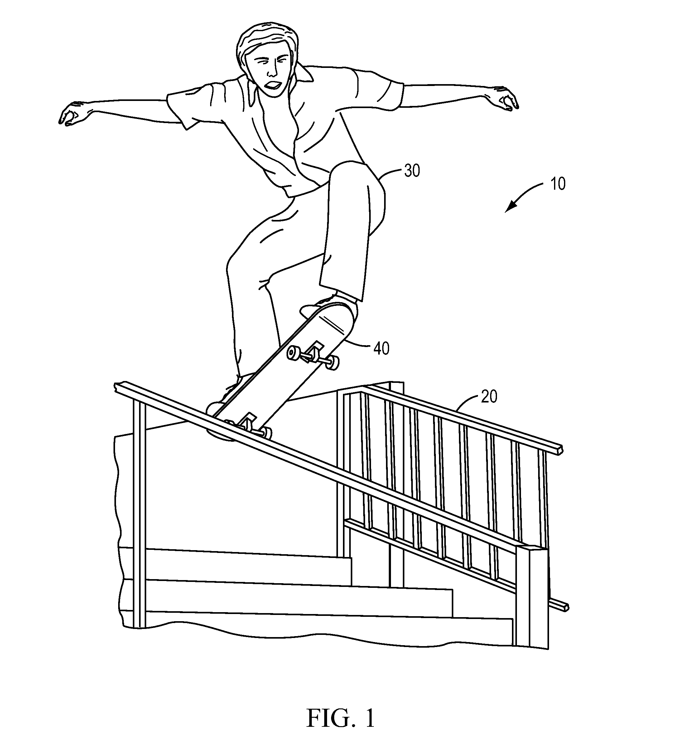
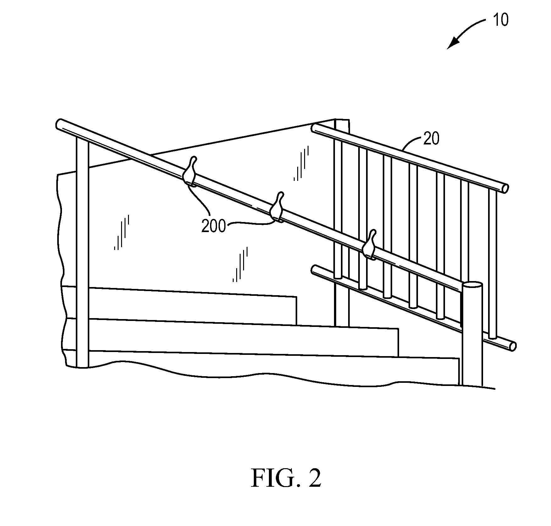
FIELD OF THE INVENTION[0001]The present invention relates generally to handrails for staircases or ramps, and more particularly to handrails that deter the use of the handrail as a slide.DESCRIPTION OF THE RELATED ART[0002]Many parks and public areas have staircases or ramps permitting easier navigation from one level to another in the park or public area. Typically, staircases 10 shown in FIG. 1 have handrails 20 on their sides and some in the center as well. Handrails must conform to certain standards so that a person can hold on to them while navigating up or down the stairs. However, handrails have the unintended consequence of providing a convenient track for skateboarders. As shown in FIG. 1, skateboarders 30 jump their skateboard 40 onto these rails 20 and slide down, possibly damaging the rail or making it unfit for its intended purpose. It would be desirable to curb the actions of skateboarders. Thus, there is a need for a modification of the handrail that would permit peop...

Claims


Application Information

Patent Timeline
IPC IPC(8): E04F11/18E04F11/00
CPCE04F2011/1868E04F11/18E04B1/72
Inventor BISHOP, PAULSCHAIBLE, JAMES BOYD
Owner BISHOP PAUL
Learn More