Regulating mechanism for drawer front

A panel adjustment and drawer technology, applied in drawers, furniture parts, home utensils, etc., can solve the problems of not meeting the aesthetic requirements of consumers, and achieve the effects of simple design, reasonable structure and low production cost

Active Publication Date: 2013-07-10
伍志勇
View PDF6 Cites 0 Cited by
  • Summary
  • Abstract
  • Description
  • Claims
  • Application Information

AI Technical Summary

Problems solved by technology

However, it can no longer meet consumers' aesthetic requirements

Method used


Image

  • Regulating mechanism for drawer front
  • Regulating mechanism for drawer front
  • Regulating mechanism for drawer front

Examples


no. 1 example

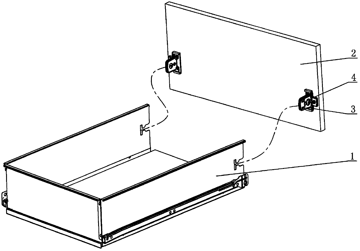
[0033] see Figure 1-Figure 6 , the drawer panel adjustment mechanism includes a connector 3 connecting the drawer side panel 1 and the drawer panel 2, and a slide seat 4 that can adjust the left and right positions of the drawer side panel 1 and the drawer panel 2 is arranged between the drawer panel 2 and the connector 3 .

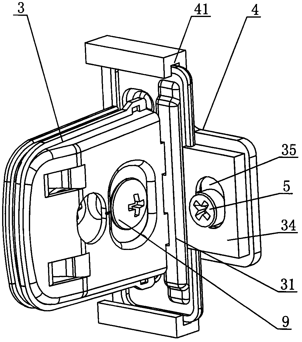
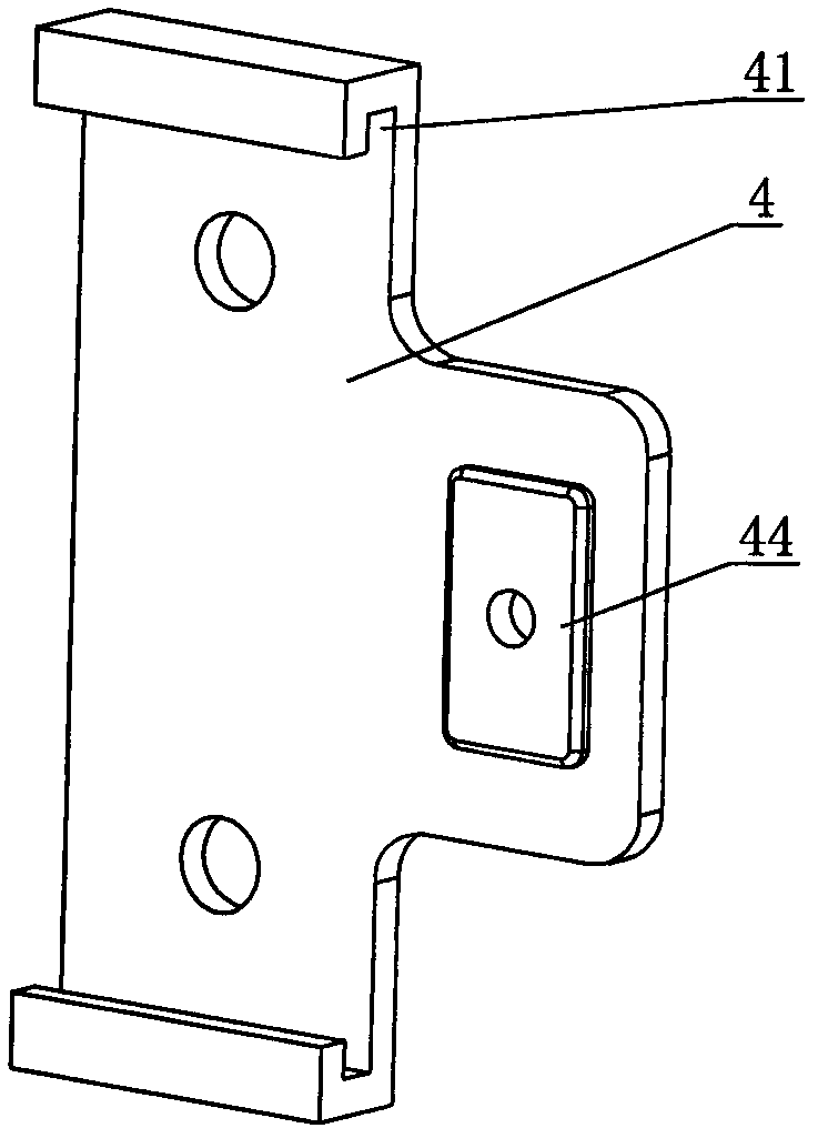
[0034] Sliding seat 4 is fixed on the drawer panel 2 back side by screw or rivet, or buckle, or welding, and one end of connector 3 can be slidably connected with sliding seat 4 left and right, and the other end is connected with the left and right side plates of drawer side plate 1. The sliding seat 4 is plate-shaped, and its upper and lower ends are respectively provided with bending parts, and the bending parts are U-shaped sliding grooves 41 . One end of the connecting piece 3 connected to the sliding seat 4 is a sliding piece 31 , which is slidably connected in the U-shaped sliding groove 41 .

[0035] One side of the slide seat 4 is provided with...

no. 2 example

[0038] see Figure 7-Figure 10 , the main difference between this drawer panel adjustment mechanism and the first embodiment is that a first adjustment block 44' is bent on one side of the slide seat 4, and an adjustment screw 6 is arranged on the first adjustment block 44'; the connector 3 The sliding piece 31 is provided with a second adjusting block 34' parallel to the first adjusting block 44'. In this embodiment, the end of the adjustment screw 6 is provided with a bayonet pin 61, and the bayonet pin 61 extends into the second adjustment block 34'; The technical effect is the same. Other unmentioned parts are the same as the first embodiment and will not be repeated.

no. 3 example

[0040] see Figure 11-Figure 14 , the main difference between this drawer panel adjustment mechanism and the first embodiment is that the upper and lower ends of the sliding seat 4 are respectively provided with pins 42 horizontally; connect. Other unmentioned parts are the same as the first embodiment and will not be repeated.


PUM


Abstract

The invention discloses a regulating mechanism for a drawer front. The regulating mechanism comprises a connecting piece for connecting a drawer side and a drawer front, and a slide seat capable of regulating the lateral positions of the drawer side and the drawer front is arranged between the drawer front and the connecting piece; the slide seat is fixed on the back face of the drawer front by using screws or rivets or in a way of fastening or welding, one end of the connecting piece can be connected with the slide seat in a leftward and rightward sliding manner, and the other end of the connecting piece is connected with left and right side boards of the drawer side; and a connecting sheet and a cover board extend out from a slide sheet of the connecting piece and used for clamping the drawer side, a second eccentric nail capable of regulating the vertical positions of the drawer side and the drawer front is arranged between the connecting sheet and the cover board, the connecting sheet and the cover board are connected by a coupling screw, and the coupling screw is sleeved with a spring. In the invention, through regulating the lateral and vertical positions of the drawer side and the drawer front, the assembling of the drawer front is tidier and more beautiful; and the regulating mechanism disclosed by the invention has the characteristics of simple design, reasonable structure, low production cost, and quickness for assembly.

Description

technical field [0001] The invention relates to a drawer, in particular to a drawer panel adjustment mechanism. Background technique [0002] On October 18, 2006, I disclosed a connection mechanism for a drawer slide rail in Chinese Patent Document No. CN2827132, which includes a slide rail side plate clamped between the cover plate and the installation connecting piece, the slide rail side plate and the drawer rollers There is an eccentric nail that can adjust the upper and lower positions of the side plate of the slide rail between the cover plate and the installation connection piece. The cover plate and the installation connection piece are connected by connecting screws. The connection screws are sleeved with pressure springs, and the cover plate is inserted on the mounting tab. A pressure spring is sheathed at the position where the connecting screw is located between the cover plate and the installation connecting piece. It can realize the adjustment of the upper an...

Claims


Application Information

Patent Timeline
Patent Type & Authority Patents(China)
IPC IPC(8): A47B88/00
Inventor 伍志勇
Owner 伍志勇
Why Eureka
Try Eureka