Drawer Position Adjustment Mechanism

A technology of adjusting mechanism and drawer, applied in the direction of drawers, furniture parts, household utensils, etc., can solve the problem that the back of the front panel and the cabinet body are difficult to stick to each other, the front panel and the cabinet body cannot be fully abutted, the drawer cannot be shielded, and the Save items and other issues to achieve the effect of quick adjustment, easy implementation and reliable performance

Active Publication Date: 2016-02-17
伍志勇
View PDF7 Cites 0 Cited by
  • Summary
  • Abstract
  • Description
  • Claims
  • Application Information

AI Technical Summary

Problems solved by technology

It is said that the structure is provided with slots for fixing the bottom plate on the side plate, and the bottom plate directly acts on the moving slide rail after assembly, so that the force on the drawer is more uniform, the working loss of each component is smaller, and the service life is longer. Moreover, the side panels and the moving slide rails are detachably connected by a detachable locking mechanism. The disassembly and assembly of the two is quick and convenient, and the manufacturing and maintenance costs are low, which is conducive to the integrated design of the drawer and makes the drawer more tidy and beautiful. However, after the front panel is assembled on the side panel through the front connector, its angular position cannot be adjusted. In the actual assembly process of the drawer, it is difficult to achieve mutual closeness between the back of the front panel and the cabinet, so that the front panel and The cabinets cannot be fully contacted, so that the drawers cannot play a better role in shielding and storing items

Method used


Image

  • Drawer Position Adjustment Mechanism
  • Drawer Position Adjustment Mechanism
  • Drawer Position Adjustment Mechanism

Examples


Embodiment Construction

[0021] The present invention will be further described below in conjunction with the accompanying drawings and embodiments.

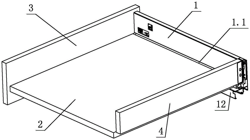
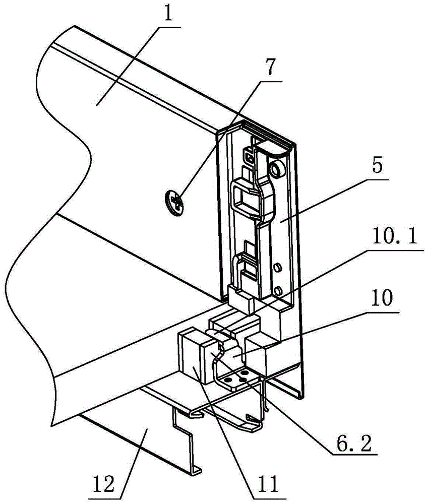
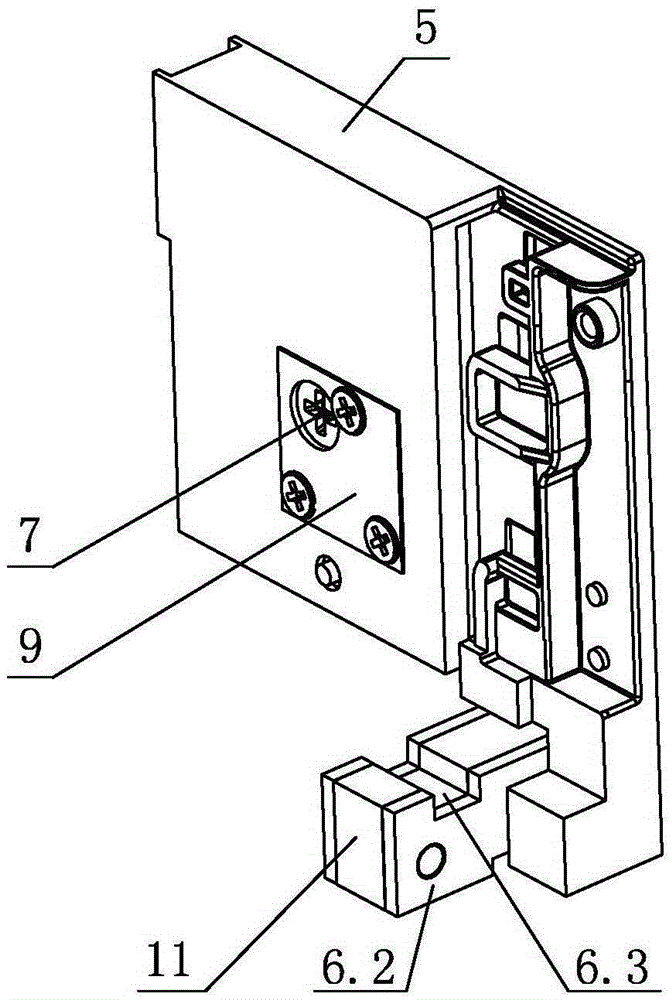
[0022] see figure 1 - Figure 7 , the position adjustment mechanism of the drawer, including a side plate 1, a bottom plate 2 and a slide rail assembly for opening and closing the drawer, the side plate 1 is provided with a front connector connecting the front panel 3 and a rear connector connecting the back panel 4 5. The side plate 1 is provided with a slot 1.1, the bottom plate 2 is assembled on the slot 1.1, and the rear connector 5 is provided with an adjustment device for adjusting the height of the drawer. The adjustment device is provided with an extension 6.2 and supported on the slide rail On the moving slide rail 12 of the assembly, the rear end of the moving slide rail 12 is provided with a positioning piece 10, and at least when assembled, it is connected with the extension part 6.2; the front part of the moving slide rail 12 is provided w...


PUM


Abstract

The invention discloses a position adjustment mechanism of a drawer. The position adjustment mechanism comprises a side plate, a bottom plate and a slide rail assembly for opening and closing the drawer, wherein a front connecting piece connected with a front panel and a rear connecting piece connected with a rear back plate are arranged on the side plate; a groove is formed in the side plate; the bottom plate is assembled on the groove; an adjustment device for adjusting the height of the drawer is arranged on the rear connecting piece; an extending part is arranged on the adjustment device and is supported on a moving slide rail of the slide rail assembly; a positioning piece is arranged at the rear end of the moving slide rail and is connected with the extending part at least in a matched way when being assembled; a bump is arranged at the front part of the moving slide rail and forms a step together with the upper surface of the moving slide rail; the bottom of the bottom plate is supported on the bump; a tilt angle, relative to a motion direction of the slide rail assembly, of the drawer is adjusted through the adjustment device. According to the structural improvement, a user can conveniently and orderly adjust the position of the drawer at any time according to the needs, the assembly effect of the front panel and a cabinet body is relatively tidy and attractive, and the practicality is high.

Description

technical field [0001] The invention relates to a position adjustment mechanism, in particular to a drawer position adjustment mechanism. Background technique [0002] Chinese Patent Document No. CN103142043A disclosed on June 12, 2013 a detachable locking mechanism for drawer slide rails and side panels, which includes side panels, bottom panels, and slide rail components for opening and closing drawers. It is provided with a front connector for connecting the front panel and a rear connector for connecting the back panel. The side plate is provided with a slot for accommodating the bottom plate. The bottom plate is set in the slot and acts on the moving slide rail of the slide rail assembly. ; There is a detachable locking mechanism between the side plate and the moving slide rail, and the moving slide rail is detachably connected with the side plate through the locking mechanism. It is said that the structure is provided with slots for fixing the bottom plate on the side...

Claims


Application Information

Patent Timeline
Patent Type & Authority Patents(China)
IPC IPC(8): A47B88/00A47B88/04
Inventor 伍志勇
Owner 伍志勇
Why Eureka
Try Eureka