Stirring rotating body and stir device
A technology of rotating body and agitator, which is applied to mixers with rotating agitating devices, transportation and packaging, mixing/kneading with vertical installation tools, etc., which can solve the problems of easy drop in agitation capacity, reaction force, and low impeller flow rate and other issues to achieve safe and efficient mixing
- Summary
- Abstract
- Description
- Claims
- Application Information
AI Technical Summary
Problems solved by technology
Method used
Image
Examples
no. 1 approach
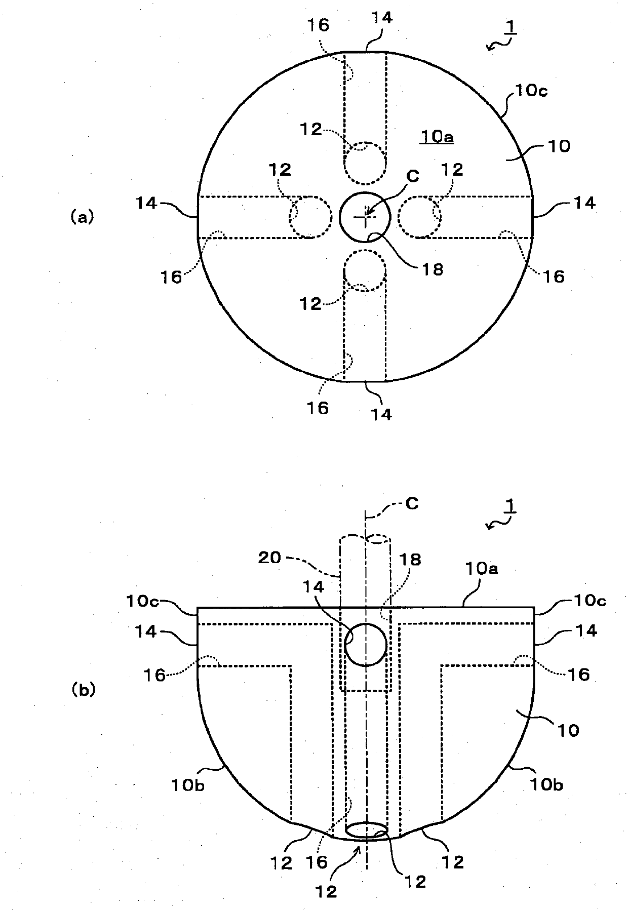
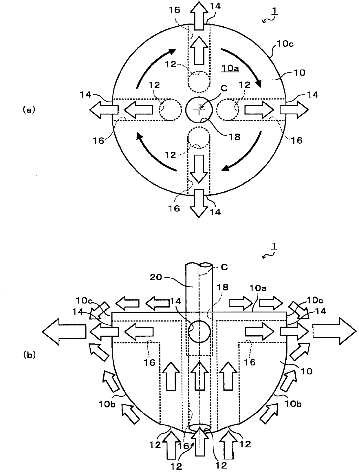
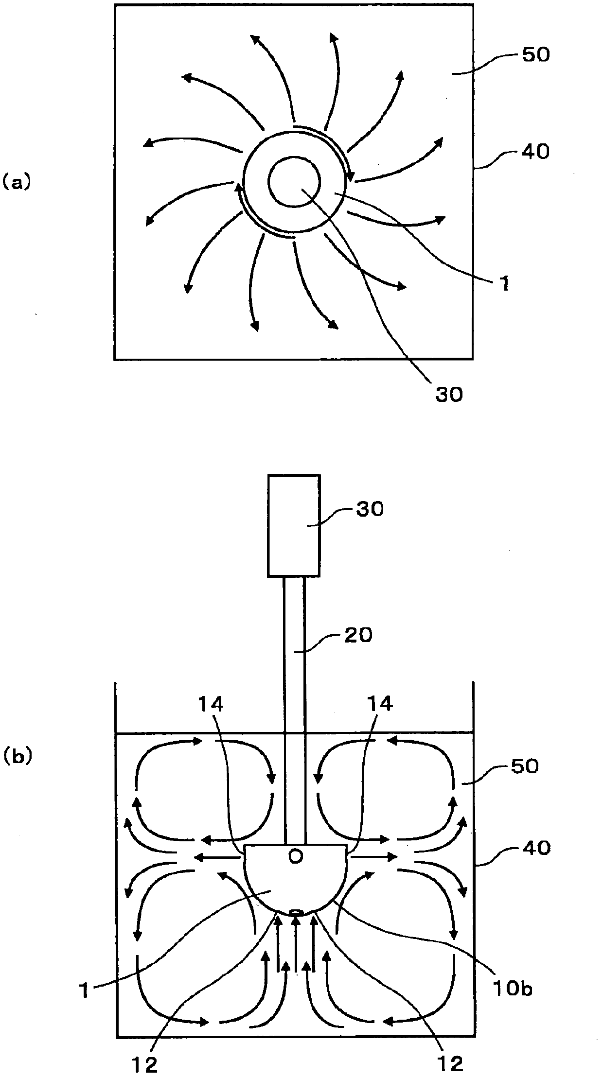
[0077] First, the structure of the stirring rotating body 1 according to the first embodiment of the present invention will be described. figure 1 (a) is a top view of the rotating body 1 for stirring, figure 1 (b) is a front view of the rotating body 1 for stirring (the side view is the same). As shown in the accompanying drawings, the stirring rotating body 1 includes: a roughly hemispherical body 10, a plurality of suction ports 12 arranged on the surface of the body 10, and a plurality of discharge ports 14 arranged on the surface of the body 10, formed inside the body 10 A flow path 16 that connects the suction port 12 and the discharge port 14 .
[0078] In this example, the shape of the body 10 is substantially hemispherical, specifically, the bottom surface 10b of one side of the disk is formed into a spherical shape. At the center of the bottom surface 10a on the other side of the main body 10, a connecting portion 18 for connecting a drive shaft 20 of a driving dev...
no. 2 Embodiment approach
[0123] Next, the structure of the stirring rotating body 100 according to the second embodiment of the present invention will be described. Figure 12 (a) is a plan view of the rotating body 100 for stirring, Figure 12 (b) is a front view of the rotating body 100 for stirring (the side view is the same), Figure 12 (c) is a bottom view of the rotating body 100 for stirring. As shown in the accompanying drawings, the rotating body 100 for stirring includes: a cylindrical body 110; a plurality of suction ports 112 arranged on the surface of the body 110 (bottom surface 110b); a plurality of discharge ports 114 arranged on the surface of the body 110 (side surface 110c) ; Formed inside the main body 110 and connecting the flow path 116 of the suction port 112 and the discharge port 114 .
[0124]The main body 110 is formed in a 12-prism shape by providing 12 protrusions 110d on the outer peripheral surface (side surface 110c) of the cylinder (details will be described later). ...
no. 3 approach
[0200] Next, the structure of the stirring rotating body 300 according to the third embodiment of the present invention will be described. Figure 32 (a) is a plan view of the rotating body 300 for stirring, Figure 32 (b) is a front view of the rotating body 300 for stirring (the side view is the same), Figure 32 (c) is a bottom view of the rotating body 300 for stirring. Figure 33 It is a partial sectional view of the rotating body 300 for stirring. As shown in the figure, the rotating body 300 for stirring includes a hemispherical body 310; a plurality of suction ports 312 arranged on the surface of the body 310; a plurality of discharge ports 314 arranged on the surface of the body 310; Port 312 and flow path 316 of discharge port 314.
[0201] In this example, the body 310 is in the shape of a sphere divided into two. Therefore, the surface of the body 310 has a planar upper surface 310 a perpendicular to the central axis C of the body 310 , and a spherical inclined...
PUM
 Abstract
Description
Claims
Application Information
 - R&D
- Intellectual Property
- Life Sciences
- Materials
- Tech Scout
- Unparalleled Data Quality
- Higher Quality Content
- 60% Fewer Hallucinations
Browse by: Latest US Patents, China's latest patents, Technical Efficacy Thesaurus, Application Domain, Technology Topic, Popular Technical Reports.
© 2025 PatSnap. All rights reserved.Legal|Privacy policy|Modern Slavery Act Transparency Statement|Sitemap|About US| Contact US: help@patsnap.com


