Fiber conveying device applied in fiber assisted fracturing process of oil-gas well and operating method for fiber conveying device
A conveying device and fiber technology, which is used in earth-moving drilling, wellbore/well components, and production fluids, etc., can solve the problems of large volume of pneumatic conveying device, large waste of fiber, unfavorable operation and construction, etc. Small floor area and the effect of preventing fiber exposure
- Summary
- Abstract
- Description
- Claims
- Application Information
AI Technical Summary
Problems solved by technology
Method used
Image
Examples
Embodiment 1
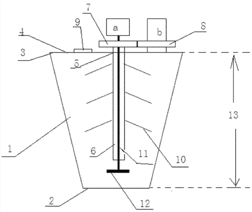
[0031] A fiber conveying device used in the fiber-assisted fracturing process of oil and gas wells, including a conveying chamber 1 with a positive conical shape, a motor a and a motor b, the small end 2 of the conveying chamber 1 and the sand mixing tank The top is fixedly connected, the feeding chamber 1 is connected with the sand mixing tank, a top cover 4 is arranged at the big end 3 of the feeding chamber 1, a stirring hole 5 is arranged at the center of the top cover 4, and a stirring hole 5 is arranged on the inner wall of the stirring hole 5 Bearings are fixedly arranged on the top, and the hollow shaft 6 penetrates the top cover 4 and is arranged in the material delivery chamber 1 through the bearing. The upper part of the hollow shaft 6 is provided with a driven gear 7, and the top cover 4 is provided with a motor b. A driving gear 8 is arranged on the b, and the driving gear 8 is meshed with the driven gear 7 for transmission connection; the top cover 4 is also provi...
Embodiment 2
[0034] A working method of the fiber conveying device as described in embodiment 1, comprising the following steps:
[0035] (1) The small end 2 of the feeding chamber of the fiber conveying device is fixedly connected to the top of the sand mixing tank, so that the feeding chamber 1 communicates with the sand mixing tank;
[0036] (2) Connect the fiber conveying device to the power supply, motor a drives the stirring shaft 11 and the stirring bar 12 to rotate at a speed of 2000 rpm; motor b drives the hollow shaft 6 and the stirring inclined bar 10 to rotate at a speed of 100 rpm ; The rotation direction of the hollow shaft 6 and the stirring bar 12 is the same;
[0037] (3) Put the fiber into the feeding chamber 1 along the feed port 9, and the speed of putting the fiber in is 0.1-100g / min.
Embodiment 3
[0039] A fiber conveying device as described in Example 1, the difference is that the length of the stirring slant 10 is 10 cm, and the angle between the stirring slant 10 and the hollow shaft 6 is 45°; The rotation speed of the hollow shaft 6 is 50 revolutions / min; the length of the stirring cross bar 12 is 12 cm; the rotation speed of the stirring cross bar 12 is 4000 revolutions / min.
[0040] The diameter of the small end 2 of the delivery cavity 1 of the truncated conical shape is 25cm; the diameter of the large end 3 of the delivery cavity 1 of the truncated cone shape is 60cm; the vertical height 13 of the delivery cavity 1 of the truncated cone shape is 62.5cm. cm.
PUM
 Abstract
Description
Claims
Application Information
 - R&D
- Intellectual Property
- Life Sciences
- Materials
- Tech Scout
- Unparalleled Data Quality
- Higher Quality Content
- 60% Fewer Hallucinations
Browse by: Latest US Patents, China's latest patents, Technical Efficacy Thesaurus, Application Domain, Technology Topic, Popular Technical Reports.
© 2025 PatSnap. All rights reserved.Legal|Privacy policy|Modern Slavery Act Transparency Statement|Sitemap|About US| Contact US: help@patsnap.com

