Fiber conveying device applied in fiber assisted fracturing process of oil-gas well and operating method for fiber conveying device

A technology for conveying devices and oil and gas wells, which is applied in the direction of earthwork drilling, wellbore/well components, and production fluids, etc. It can solve the problems of large volume of pneumatic conveying devices, unfavorable operation and construction, and large amount of fiber waste. The effect of preventing fiber exposure and occupying a small area

Active Publication Date: 2012-07-04
CHINA UNIV OF PETROLEUM (EAST CHINA)
View PDF6 Cites 7 Cited by
  • Summary
  • Abstract
  • Description
  • Claims
  • Application Information

AI Technical Summary

Problems solved by technology

The pneumatic conveying device currently used in the mixed injection fiber fracturing technology has the following problems: (1) The pneumatic conveying device is bulky and requires a special vehicle for transportation; (2) Using a fan for fiber conveying is costly and wastes a lot of fiber. And it is easy to cause environmental pollution; (3) the power supply used is a 380v power supply, which is not conducive to the operation and construction of fracturing sites

Method used


Image

  • Fiber conveying device applied in fiber assisted fracturing process of oil-gas well and operating method for fiber conveying device
  • Fiber conveying device applied in fiber assisted fracturing process of oil-gas well and operating method for fiber conveying device

Examples


Embodiment 1

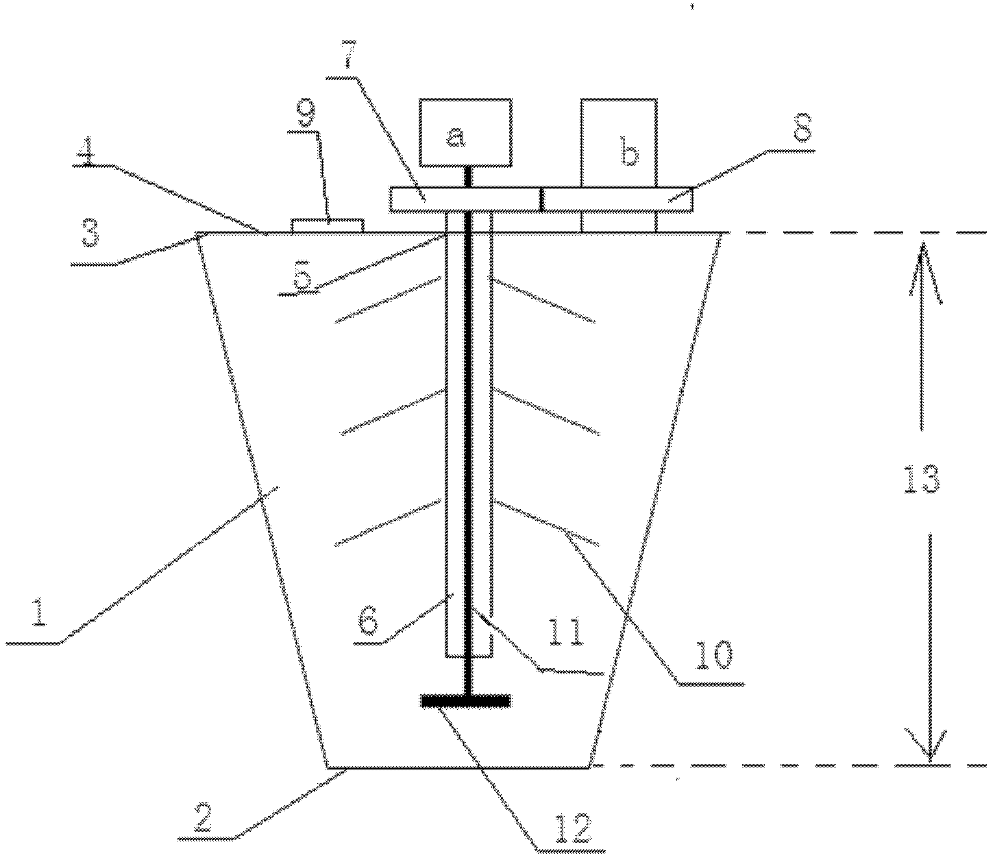
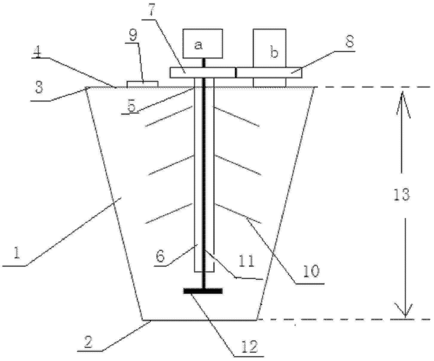
[0031] A fiber conveying device used in the fiber-assisted fracturing process of oil and gas wells, including a conveying chamber 1 with a positive conical shape, a motor a and a motor b, the small end 2 of the conveying chamber 1 and the sand mixing tank The top is fixedly connected, the feeding chamber 1 is connected with the sand mixing tank, a top cover 4 is arranged at the big end 3 of the feeding chamber 1, a stirring hole 5 is arranged at the center of the top cover 4, and a stirring hole 5 is arranged on the inner wall of the stirring hole 5 Bearings are fixedly arranged on the top, and the hollow shaft 6 penetrates the top cover 4 and is arranged in the material delivery chamber 1 through the bearing. The upper part of the hollow shaft 6 is provided with a driven gear 7, and the top cover 4 is provided with a motor b. A driving gear 8 is arranged on the b, and the driving gear 8 is meshed with the driven gear 7 for transmission connection; the top cover 4 is also provi...

Embodiment 2

[0034] A working method of the fiber conveying device as described in embodiment 1, comprising the following steps:

[0035] (1) The small end 2 of the feeding chamber of the fiber conveying device is fixedly connected to the top of the sand mixing tank, so that the feeding chamber 1 communicates with the sand mixing tank;

[0036] (2) Connect the fiber conveying device to the power supply, motor a drives the stirring shaft 11 and the stirring bar 12 to rotate at a speed of 2000 rpm; motor b drives the hollow shaft 6 and the stirring inclined bar 10 to rotate at a speed of 100 rpm ; The rotation direction of the hollow shaft 6 and the stirring bar 12 is the same;

[0037] (3) Put the fiber into the feeding chamber 1 along the feed port 9, and the speed of putting the fiber in is 0.1-100g / min.

Embodiment 3

[0039] A fiber conveying device as described in Example 1, the difference is that the length of the stirring slant 10 is 10 cm, and the angle between the stirring slant 10 and the hollow shaft 6 is 45°; The rotation speed of the hollow shaft 6 is 50 revolutions / min; the length of the stirring cross bar 12 is 12 cm; the rotation speed of the stirring cross bar 12 is 4000 revolutions / min.

[0040] The diameter of the small end 2 of the delivery cavity 1 of the truncated conical shape is 25cm; the diameter of the large end 3 of the delivery cavity 1 of the truncated cone shape is 60cm; the vertical height 13 of the delivery cavity 1 of the truncated cone shape is 62.5cm. cm.


PUM


Abstract

The invention relates to a fiber conveying device applied in the fiber assisted fracturing process of an oil-gas well. The fiber conveying device comprises a delivery cavity which is in a shape of a right conical platform, a motor a and a motor b, wherein the small end of the delivery cavity is fixedly connected with the top of a sand mixing tank; the delivery cavity is communicated with the sand mixing tank; a top cover is arranged at the large end of the delivery cavity; a stirring hole is formed in the center of a circle of the top cover; a bearing is fixedly arranged on the inner wall of the stirring hole; a hollow shaft passes through the top cover and is arranged in the delivery cavity by the bearing; a driven gear is arranged on the upper part of the hollow shaft; the motor b is arranged on the top cover; a driving gear is arranged on the motor b; the driving gear is in transmission connection with the driven gear; and a feeding hole which is communicated with the delivery cavity is also formed in the top cover. By the fiber conveying device, fibers and materials in the sand mixing tank can be mixed safely and efficiently, the threat to the health of staff due to the exposure of the fibers is avoided, environmental pollution is reduced, the using amount of the fibers is reduced, and the production cost and operating cost are low.

Description

technical field [0001] The invention relates to a fiber conveying device and a working method thereof used in the fiber-assisted fracturing process of oil and gas wells, and belongs to the technical field of oil exploitation. Background technique [0002] There is a contradiction between accelerating fluid drainage and controlling proppant reflux and regurgitation in fracturing wells: too fast fluid drainage may exceed the critical sand flow rate, resulting in proppant reflux; too low fluid drainage will lead to increased drainage time and The flowback rate has declined, and solving this contradiction has always been a difficult problem. The mixed injection fiber fracturing technology (fiber-reinforced sand fracturing technology) can increase the critical sand flow rate of sand-filled fractures, increase the flowback speed after fracturing, and effectively prevent proppant backflow. [0003] The mixed-injection fiber fracturing technology refers to mixing the fiber material...

Claims


Application Information

Patent Timeline
Patent Type & Authority Applications(China)
IPC IPC(8): E21B43/267
Inventor 温庆志战永平罗明良潘晓军胡蓝霄贾长贵
Owner CHINA UNIV OF PETROLEUM (EAST CHINA)
Why Eureka
Try Eureka