
Deinterlacing method

A de-interlacing, all-direction technology, applied in the field of image processing, can solve the problems of image distortion, boundary judgment misjudgment, jaggies at the object boundary and motion sequence flicker, etc., to achieve accurate interpolation results and good de-interlacing effect.

Active Publication Date: 2014-05-21
上海顺久电子科技有限公司
View PDF8 Cites 0 Cited by
  • Summary
  • Abstract
  • Description
  • Claims
  • Application Information

AI Technical Summary

Problems solved by technology

The main challenge of 2D technology is how to restore the boundary texture details of the image as much as possible and reduce the loss of image resolution as low as possible
The main problem with this type of interpolation method is that the reconstructed image is often heavily distorted, resulting in jagged object boundaries in the resulting image and flickering during playback of motion sequences
In addition, the existing technology also proposes a boundary-based interpolation method. Although the boundary interpolation method can provide higher resolution, the boundary judgment often leads to misjudgment, and wrong boundary information will greatly damage the quality of the reconstructed image.

Method used


Image

  • Deinterlacing method
  • Deinterlacing method
  • Deinterlacing method

Examples


Embodiment approach

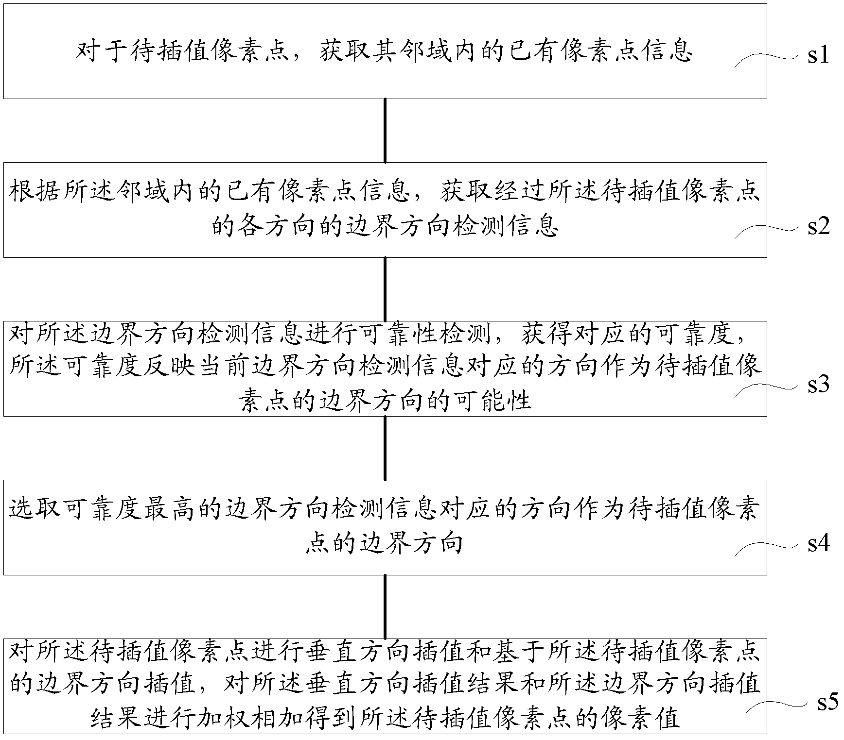
[0021] figure 1 An embodiment of the deinterlacing method of the present invention is shown, which includes:

[0022] Execute step s1, for the pixel to be interpolated, obtain the existing pixel information in its neighborhood;

[0023] Execute step s2, according to the existing pixel point information in the neighborhood, obtain the boundary direction detection information in each direction passing through the pixel point to be interpolated;

[0024] Executing step s3, performing reliability detection on the boundary direction detection information to obtain a corresponding reliability, the reliability reflecting the possibility that the direction corresponding to the current boundary direction detection information is used as the boundary direction of the pixel to be interpolated;

[0025] Execute step s4, select the direction corresponding to the boundary direction detection information with the highest reliability as the boundary direction of the pixel to be interpolated;...


PUM


Abstract

A deinterlacing method is characterized by: through reliably detecting each direction of a pixel point to be interpolated, determining possibility (reliability) of regarding the each direction as a boundary direction of the pixel point to be interpolated; selecting the direction with the highest reliability as the boundary direction of the pixel point to be interpolated; performing vertical direction interpolation and the interpolation based on the boundary direction to the pixel point to be interpolated, wherein an interpolation result is related to the reliability. Therefore, the interpolation result is accurate and a better deinterlacing effect can be obtained.

Description

technical field [0001] The invention relates to the technical field of image processing, in particular to a deinterlacing method. Background technique [0002] In order to reduce the bandwidth of the video signal and make the circuit easier to design, traditional TV systems, such as PAL / NTSC / SECAM, mostly use interlaced scanning technology. Simply put, interlaced scanning technology is to reproduce the picture in an interlaced manner. Under the interlaced scanning technology, the vertical resolution of the image is low, and visible disturbances such as edge flickering will inevitably occur. And, when the screen is larger, this interference is more significant. With the development of science and technology and the promotion of digital TV, modern video equipment has gradually entered the high-definition era of progressive display. To play old video content on modern display devices, it is necessary to convert interlaced video signals to progressive video signals, that is, ...

Claims


Application Information

Patent Timeline
Patent Type & Authority Patents(China)
IPC IPC(8): H04N7/01
Inventor 钟声徐杰
Owner 上海顺久电子科技有限公司
Learn More