Roughing pump method for a positive displacement pump

A positive displacement pump and rough pumping technology, applied in the direction of rotary piston pump, liquid displacement machinery, pump, etc.

A positive displacement pump and rough pumping technology, applied in the direction of rotary piston pump, liquid displacement machinery, pump, etc.

CN102395792BInactive Publication Date: 2014-09-10OERLIKON LEYBOLD VACUUM

Image

  • Roughing pump method for a positive displacement pump
  • Roughing pump method for a positive displacement pump
  • Roughing pump method for a positive displacement pump

Examples


Embodiment Construction

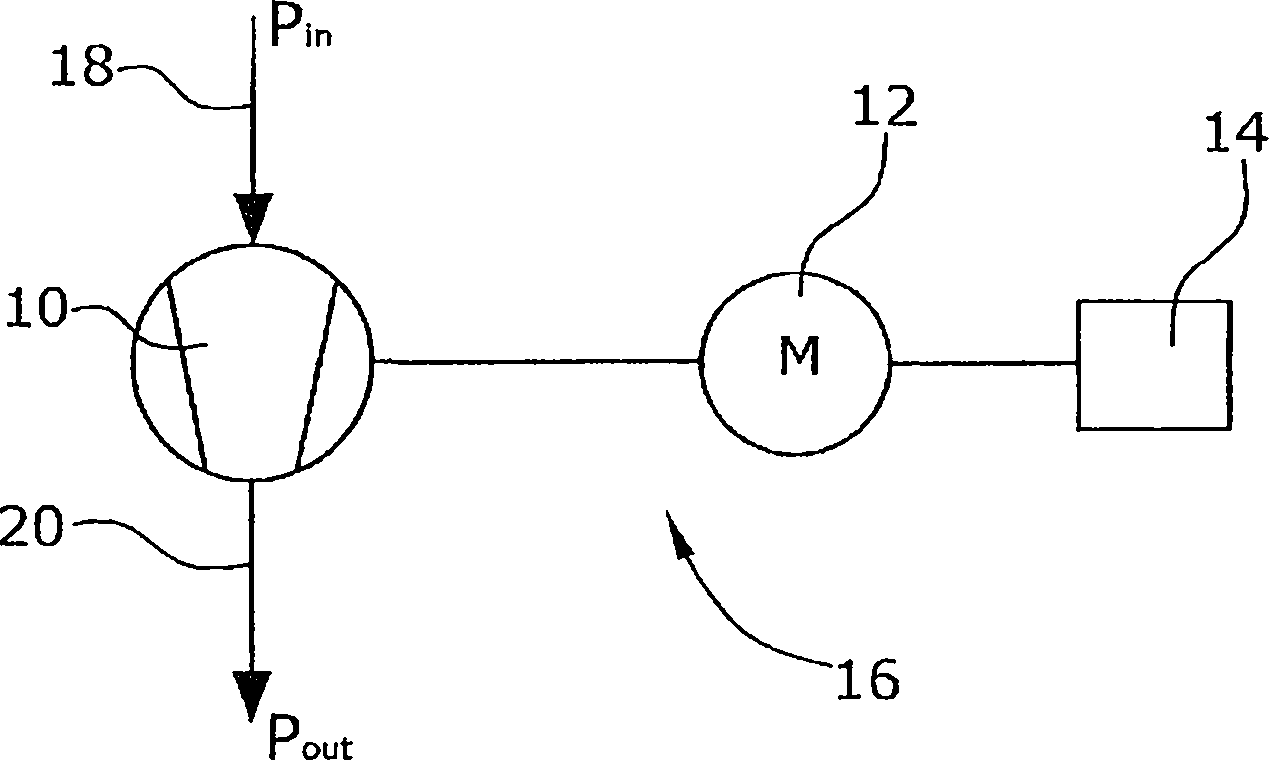
[0026] figure 1 The displacement pump device 16 shown in FIG. 1 is formed from a displacement pump 10 , a pump drive 12 for the displacement pump 10 and a control device 14 connected to the pump drive 12 . The displacement pump 10 is a Roots pump and the pump drive 12 is an electric motor. The control device 14 is an electronic converter with which the rotational speeds of the pump drive 12 and of the displacement pump 10 can be set.

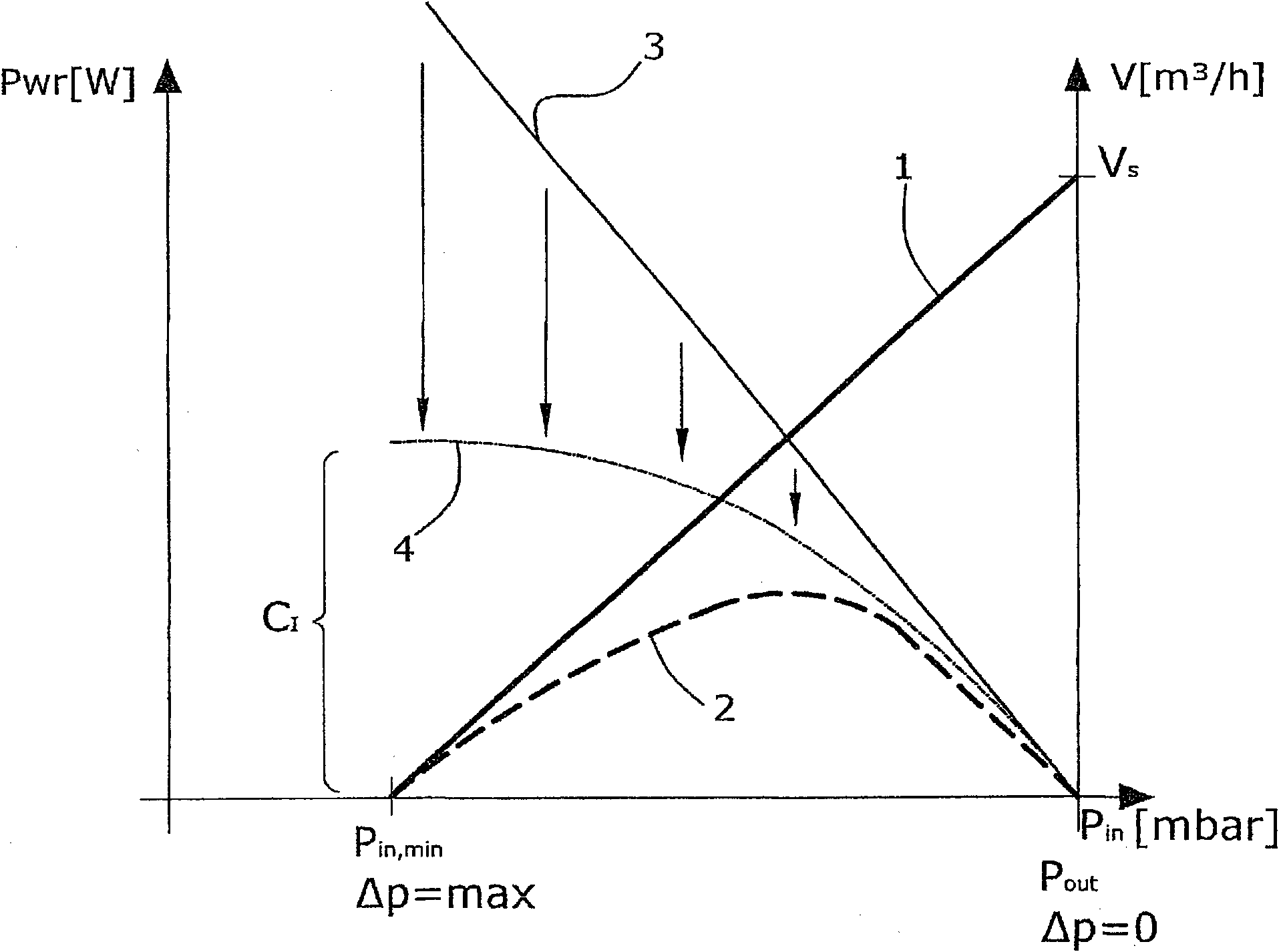
[0027] At the suction-side inlet 18 of the positive displacement pump 10, there is an inlet pressure P in the suction channel of the pump in . At the pressure-side outlet 20 of the positive displacement pump 10 , there is an outlet pressure P in the outlet channel of the positive displacement pump 10 out . as referenced below figure 2 As depicted, for the existing pressure P in and P out and the resulting differential pressure ΔP max =P out -P in , the positive displacement pump 10 is overcapacitated, so that by reducing the speed of ...


PUM


Abstract

In order to provide a simple and energy-efficient rough pumping method for a displacement pump (10), intended to generate a maximum differential pressure (ΔPmax) between the inlet (18) and the outlet (20) of the displacement pump (10), the rotational speed (Ω) of the displacement pump (10) is adjusted such that the maximum differential pressure (ΔPmax) to be generated that the power input (3, 4) of the displacement pump (10) approximates the minimum power (2) physically required for compressing the gas in order to establish the maximum differential pressure (ΔPmax).

Description

technical field [0001] The invention relates to a roughing method for a positive displacement pump and a positive displacement pump device for establishing a rough pressure difference. Background technique [0002] In the present case, a rough pressure difference is understood to mean a negative pressure difference in the sense of a rough vacuum or a positive pressure difference in the sense of a rough pressure application. Typical rough vacuums have differential pressures of up to 500 mbar in magnitude and typically vary in the range of differential pressures of 100 to 300 mbar. For a wide variety of applications, a roughing vacuum pump, usually designed as a single-shaft centrifugal compressor or a side-channel blower, is highly desirable. Side channel blowers have a defined volume flow and must be operated continuously at a continuously high rotational speed. They work on the principle of torque transmission according to Euler's energy equation for compressible fluids. ...

Claims


Application Information

Patent Timeline
10 Sep 2014
Publication
CN102395792B
IPC
F04C18/12; F04C28/08
CPC
F04C2240/40; F04C2270/02; F04C28/08; F04C18/123; F04B49/20
Inventors
彼得·比尔克