Mechanism for quickly withdrawing detection pin

A detection pin, fast technology, applied in the direction of measuring devices, mechanical devices, mechanical measuring devices, etc., can solve the problems of large number of detection pins, low detection efficiency of detection pin insertion and extraction methods, inconvenient detection of corresponding hole positions, etc. , to achieve the effect of rapid detection

Active Publication Date: 2014-01-22
CHERY AUTOMOBILE CO LTD
View PDF6 Cites 0 Cited by
  • Summary
  • Abstract
  • Description
  • Claims
  • Application Information

AI Technical Summary

Problems solved by technology

[0004] In the process of detection, they all have a common problem: the number of detection pins is large, it is inconvenient to find the corresponding hole position for detection, and the detection efficiency of the detection pin is low.

Method used


Image

  • Mechanism for quickly withdrawing detection pin
  • Mechanism for quickly withdrawing detection pin
  • Mechanism for quickly withdrawing detection pin

Examples


Embodiment Construction

[0026] In order to make the object, technical solution and advantages of the present invention clearer, the implementation manner of the present invention will be further described in detail below in conjunction with the accompanying drawings.

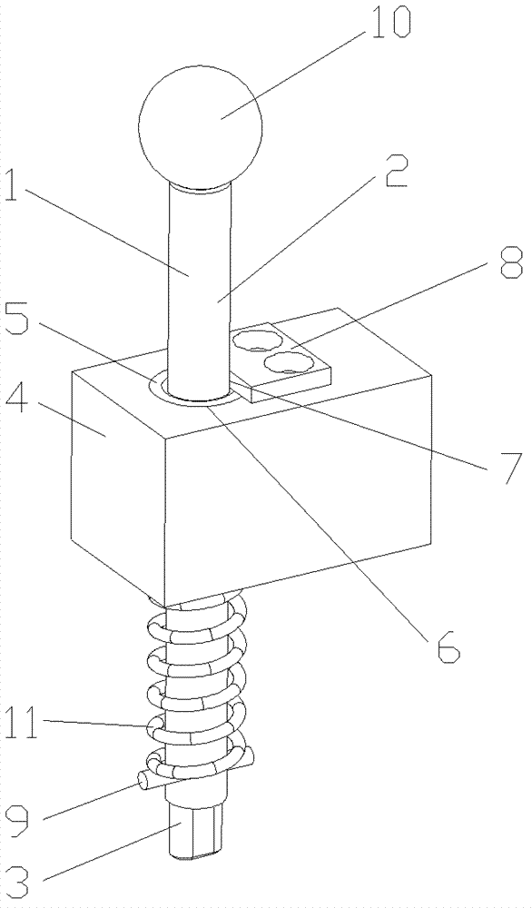
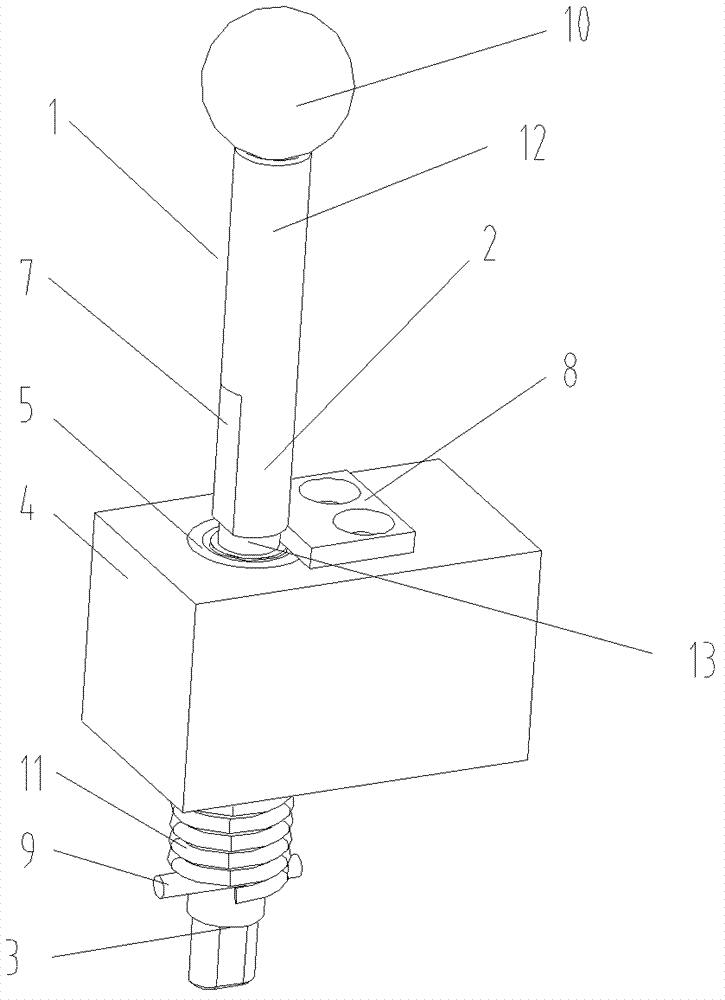
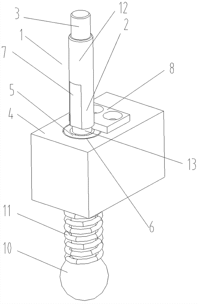
[0027] Such as figure 1 with figure 2 As shown, the detection pin mechanism includes: a limit adjustment rod 1, a positioning block 4 and a limit stopper 8. The limit adjustment rod 1 is a circular structure in cross section, and a limit protrusion 2 is formed on its upper part to detect The pin 3 is set at the lower end of the limit adjustment rod 1. The detection pin 3 in the figure is a detection pin structure used to detect special-shaped detection holes. The end of the adjustment rod 1; the positioning block 4 is used for fixed connection with the bottom plate of the inspection tool, and a circular positioning hole 6 is formed on it. Preferably, a pin sleeve 5 is arranged in the positioning hole 6, and the pin sleeve 5 is positi...


PUM


Abstract

The invention discloses a mechanism for quickly withdrawing a detection pin. The mechanism comprises a detection pin of which the shape is accordant with that of a detected hole site, and is characterized by further comprising a limit adjusting rod, a positioning block and a limit chock block, wherein a limit bump is molded on the upper part of the limit adjusting rod; the detection pin is arranged at one end of the limit adjusting rod; the positioning block is fixedly connected with a bottom plate of a detection tool; a circular positioning hole is molded on the positioning block; the limit adjusting rod is arranged in the positioning hole, and is vertical to the upper surface of the positioning block; the limit chock block is arranged on the upper end face of the positioning block, and is used for driving the detection pin to rotate by rotating the limit adjusting rod; and the lower end face of the limit bump is clamped on the upper end face of the limit chock block or the upper end face of the positioning block, so that rapid positioning detection and withdrawing of the detection pin are realized, the operation is convenient, and the detection efficiency is high.

Description

technical field [0001] The invention relates to a checking tool in mechanical processing, in particular to a quick-drawing detection pin mechanism for detecting the position of a product hole on the checking tool. Background technique [0002] In the process of designing and manufacturing product inspection tools, due to the large number of product holes and the relatively high requirements for the position of the holes, it is generally necessary to detect the position of the holes through the plug-in detection pin of the inspection tool. When using the detection pin, remove it from the tool box Take them out, and then insert them one by one into the detection holes that need to be detected. After the detection is completed, the detection pins need to be retracted into the tool box. This process needs to be repeated for each detection. [0003] In the process of realizing the present invention, the inventor finds that the prior art has at least the following disadvantages: ...

Claims


Application Information

Patent Timeline
Patent Type & Authority Patents(China)
IPC IPC(8): G01B5/00
Inventor 胡龙玲宋忠朋
Owner CHERY AUTOMOBILE CO LTD
Why Eureka
Try Eureka