Main part device of heat storage type porous medium tail gas heat energy recovery micro-emission energy-saving engine

A technology of porous media and heat energy recovery, applied in engine components, exhaust devices, combustion engines, etc., can solve the problems of less micro-emission technology and less product discovery, and achieve the effects of low cost, significant economic benefits and stable performance

Inactive Publication Date: 2012-05-23
陈明 +2
View PDF0 Cites 1 Cited by
  • Summary
  • Abstract
  • Description
  • Claims
  • Application Information

AI Technical Summary

Problems solved by technology

At present, the existing engine technologies of exhaust heat energy recovery devices are basically in the experimental sta...

Method used


Image

  • Main part device of heat storage type porous medium tail gas heat energy recovery micro-emission energy-saving engine
  • Main part device of heat storage type porous medium tail gas heat energy recovery micro-emission energy-saving engine
  • Main part device of heat storage type porous medium tail gas heat energy recovery micro-emission energy-saving engine

Examples


Embodiment Construction

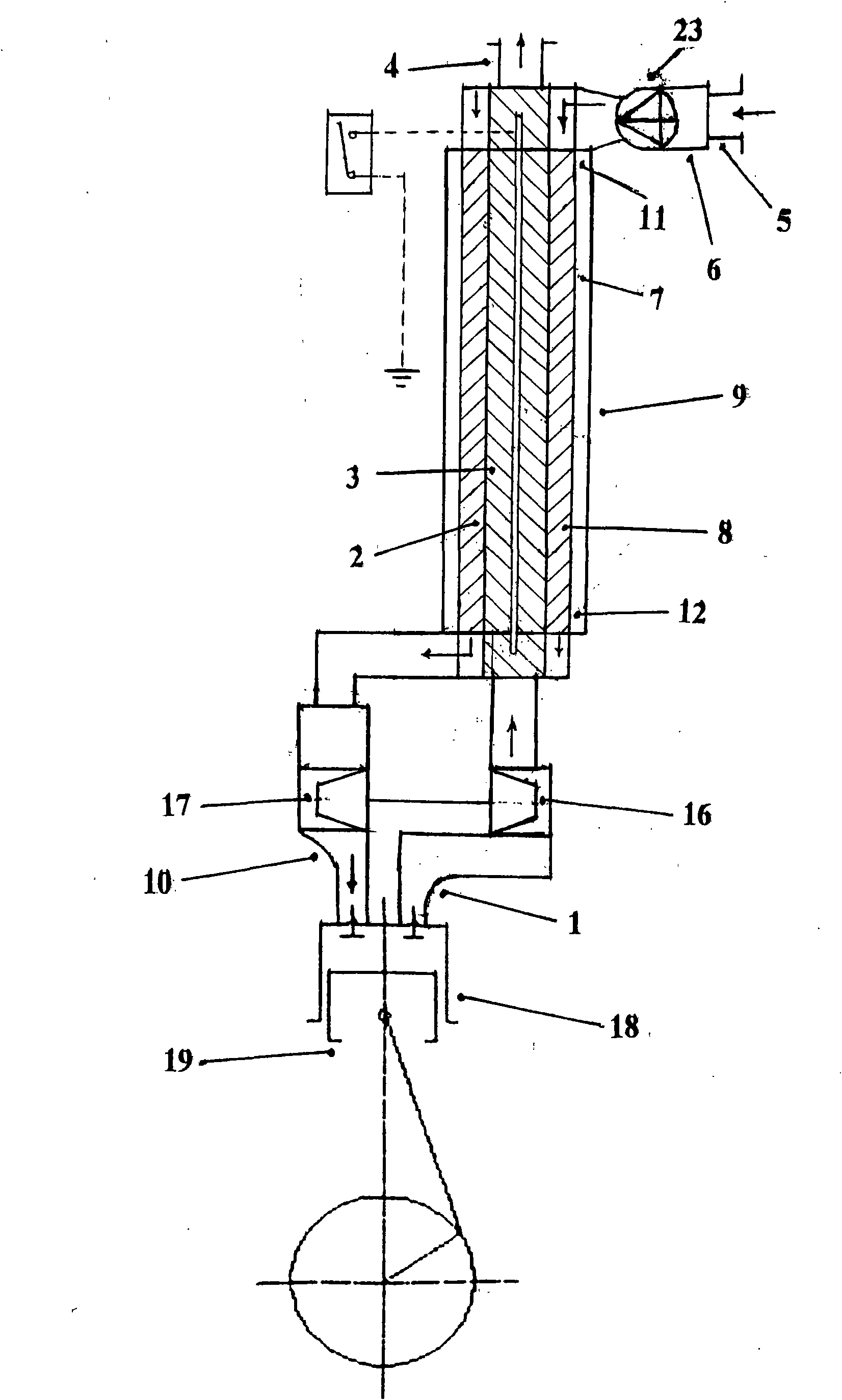
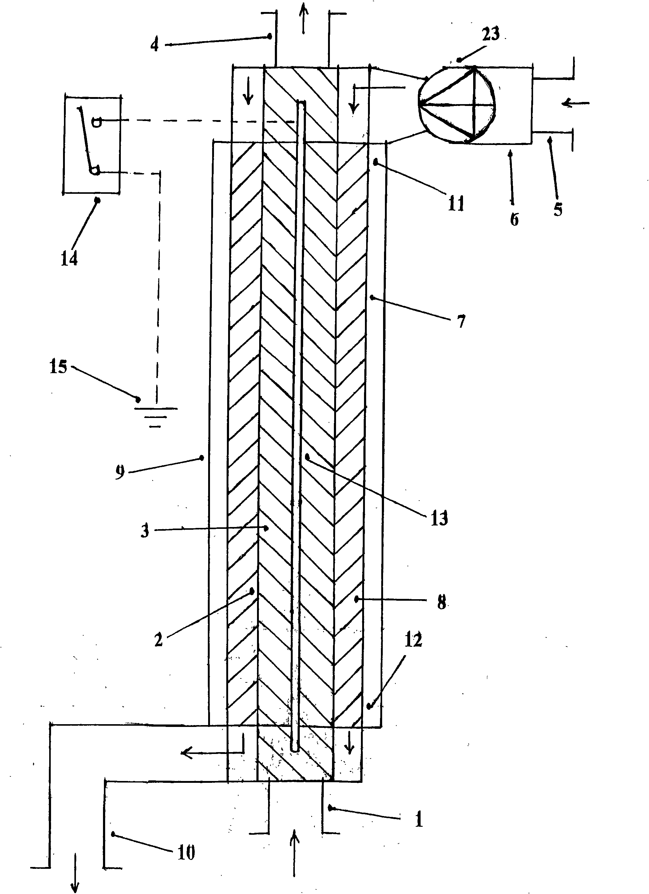
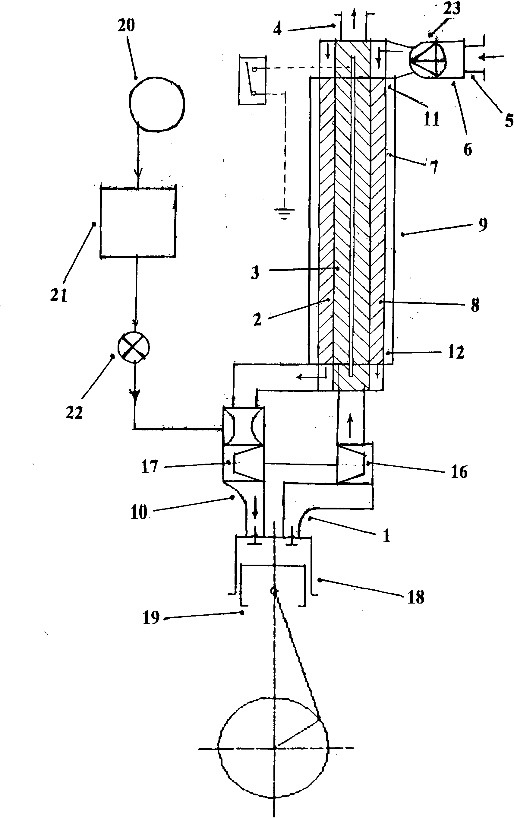
[0013] exist figure 1In the middle, the inner tube porous medium waste heat recovery regenerative body tube (2) and the inner layer porous medium regenerative body (3) are set between the high temperature exhaust gas input pipe (1) and the low temperature residual gas exhaust pipe (4). Tube Porous Media Waste Heat Recovery Heat Storage Body The tube (2) is provided with an inner layer porous medium heat storage body (3). Between the fresh low-temperature air input pipe (5) and the high-temperature air inlet inlet pipe (10) of the engine, an outer pipe porous medium waste heat recovery heat storage body pipe (7), an outer porous medium heat storage body (8), and an outer heat storage body (8) are arranged. Insulation layer (9), an outer porous medium heat storage body (8) is arranged inside the outer porous medium waste heat recovery heat storage body pipe (7), and an outer heat preservation layer is arranged outside the outer porous medium waste heat recovery heat storage body...


PUM


Abstract

The invention discloses a main part device of a heat storage type porous medium tail gas heat energy recovery micro-emission energy-saving engine, which comprises a cylinder, a piston, a tail gas inlet pipe, a tail gas exhaust pipe, an air inlet pipe, an air filter, an engine gas inlet pipe and a silencer, wherein low-temperature and high-temperature exchange is carried out in the same long pipe in a porous medium heat retainer separated at a cold end and a heat end. An inner pipe porous medium residual heat recovery heat retainer pipe and an inner layer porous medium heat retainer are arranged on an intermediate channel from a high-temperature tail gas input pipe to a low-temperature residual gas exhaust pipe; an outer pipe porous medium residual heat recovery heat retainer pipe and an outer layer porous medium heat retainer are arranged on an intermediate channel from a fresh low-temperature air input pipe to a high-temperature air guide engine gas inlet input pipe; a high-temperature combustion ash clearing electric heating rod is arranged in an intermediate channel of the inner pipe porous medium residual heat recovery heat retainer pipe; and a standby auxiliary compressor is arranged at the output end of the fresh low-temperature air input pipe. The invention is suitable for being used on an energy-saving engine.

Description

Technical field [0001] The invention relates to an uninterrupted heat-storage porous medium regenerator that uses high-temperature air to generate energy from the exhaust gas into the high-temperature air combustion technology of the engine to recover the heat energy of the engine exhaust gas, and can greatly reduce pollutants such as carbon dioxide and nitrogen oxides in the exhaust gas. The invention relates to a novel engine combination energy-saving device capable of greatly increasing output power through high-temperature and low-oxygen combustion, in particular to a regenerative porous medium tail gas heat energy recovery micro-emission energy-saving engine main component device. Background technique [0002] In the internal combustion engine, about 20% to 45% of the fuel heat taken away by the exhaust gas is completely wasted in vain and seriously pollutes the atmospheric environment. At present, the engine technologies of existing exhaust heat energy recovery devices...

Claims


Application Information

Patent Timeline
IPC IPC(8): F02M31/093F01N5/02F02M25/00F01N3/08F02B37/00
CPCY02T10/144Y02T10/16Y02T10/12
Inventor 陈明
Owner 陈明
Why Eureka
Try Eureka