
Electric connector and locking structure thereof

A technology of locking structure and electrical connector, which is applied to the parts, connections, circuits, etc. of the connection device, which can solve problems such as disengagement, engine vibration, and the vehicle cannot move and stop, so as to achieve simple operation, reliable buckle, Avoid the effect of electrical instability

Active Publication Date: 2014-05-14
HU LANE ASSOC INC
View PDF4 Cites 0 Cited by
  • Summary
  • Abstract
  • Description
  • Claims
  • Application Information

AI Technical Summary

Problems solved by technology

[0004] Since the road surface of the vehicle is not completely flat, and the engine will vibrate when it is running, the electrical connector used for the electronic control unit must be able to form an electrical connection with the complementary electrical connector firmly and Lock the relationship to avoid poor contact or disengagement of the two electrical connectors due to external factors such as jumping or vibration, making the vehicle unable to move and stop

Method used


Image

  • Electric connector and locking structure thereof
  • Electric connector and locking structure thereof
  • Electric connector and locking structure thereof

Examples


Embodiment Construction

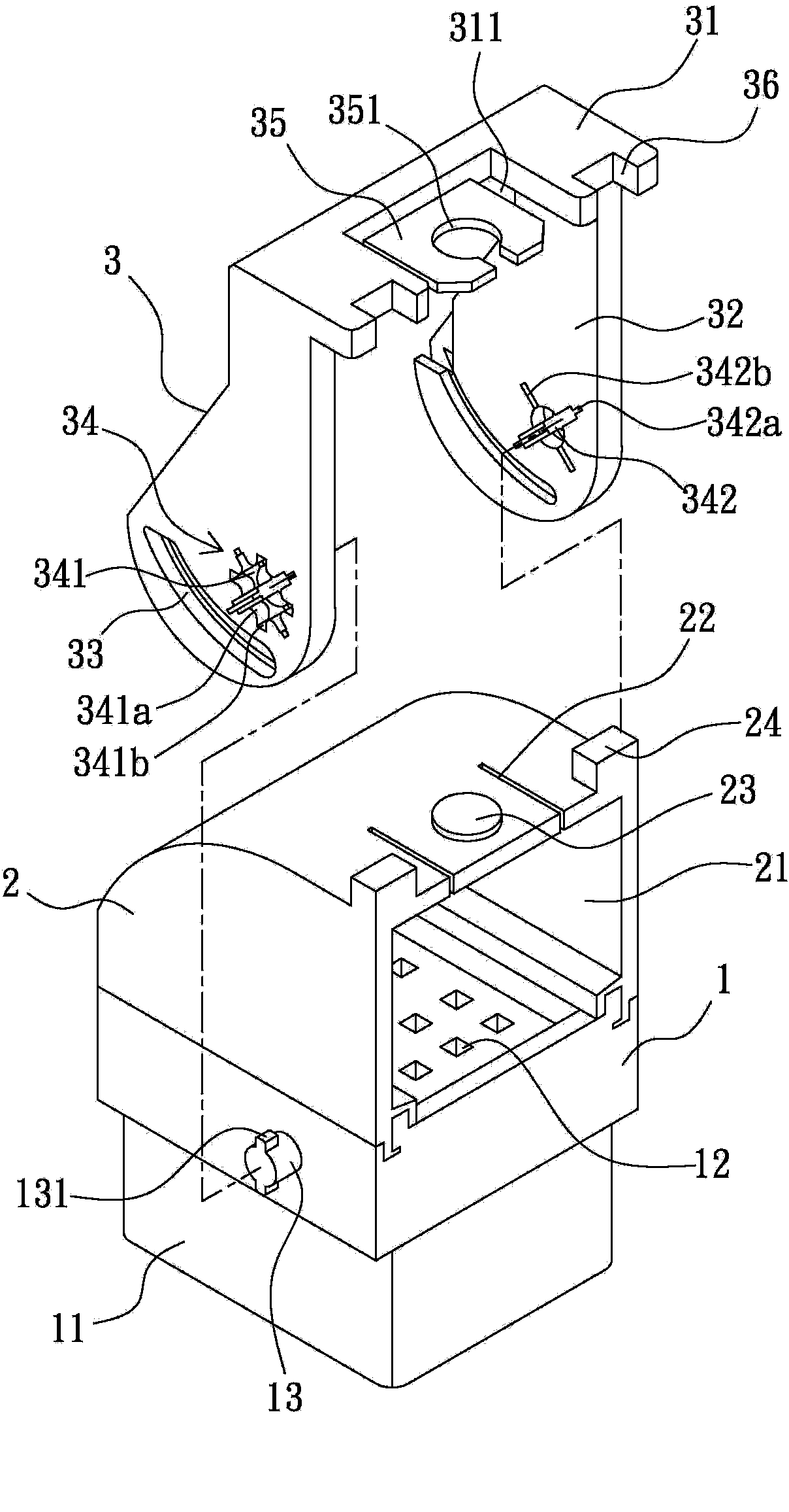
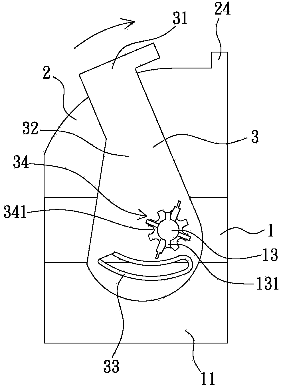
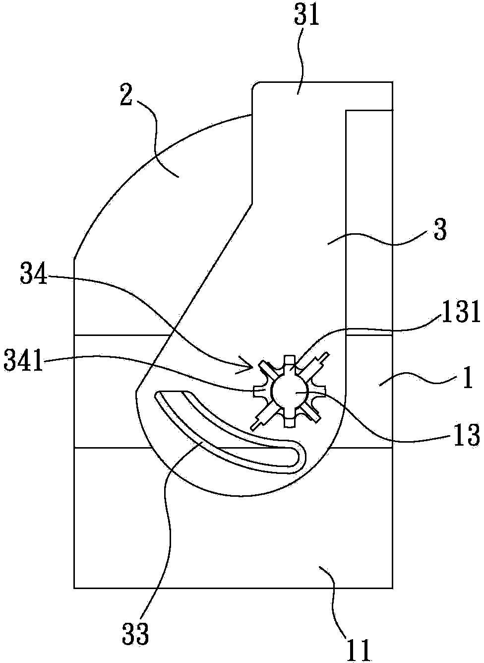
[0054] Such as Figure 1 to Figure 4b Shown is the first embodiment of the locking structure of the electrical connector of the present invention, which includes a body 1 , a cover 2 , and a rotating member 3 .

[0055] Wherein, the body 1 is made of insulating material, such as plastic. A joint part 11 protrudes from the bottom of the body 1, and the joint part 11 is used for docking with a complementary electrical connector. Therefore, more than one terminal groove 12 is longitudinally provided from the bottom surface of the joint part 11 to the top surface of the body 1, and each terminal groove 12 It is used for accommodating and positioning the contact terminals (not shown in the figure), and the wires of each contact terminal pass through the top surface of the body 1 . The locking structure after the contact terminals are installed constitutes the electrical connector of the present invention. Wherein, a pair of pivot shafts 13 protrude from the left and right sides o...


PUM


Abstract

The invention relates to a locking structure of an electric connector, which comprises a body, a cover and a rotating part. A jointing portion is arranged on the lower side of the body, more than one terminal groove is longitudinally arranged from the bottom of the jointing portion to the top of the body, terminals are mounted in the terminal grooves, a pair of pivots is protrude on two side surfaces of the body, the cover is fixedly connected to the top of the body, an opening is arranged at the front of the cover, various leads of the contact terminals penetrate out of the opening, a pair of fins is arranged at two ends of a connecting portion of the top of the rotating part in a downwards drooping manner, a pair of arc-shaped locking grooves and a pair of pivoting holes are respectively oppositely arranged at bottoms of the fins, and the pivots are pivotally connected with the pivoting holes. An elastic locking mechanism is disposed between the top edge of the opening of the cover and the connecting portion of the top of the rotating part; when the rotating part rotates towards the direction of the opening of the cover, the elastic locking mechanism is locked; and when the elastic locking mechanism is unlocked, the rotating part is pushed to reversely rotate, and unlocking is realized. The locking structure of the electric connector has the advantages that the locking structure is simple and convenient in operation, and the rotating part and the cover can be reliably fastened.

Description

technical field [0001] The invention relates to an electrical connector, in particular to a locking structure of the electrical connector and an electrical connector using the locking structure. Background technique [0002] At present, electrical connectors are widely used in electrical products, and their main purpose is to transmit power or signals. Therefore, electrical connectors have been widely used in the connection of electronic products and are indispensable components. [0003] In fact, the application of electrical connectors is not only limited to the aforementioned information products, but also widely used in the circuit system of automobiles and motorcycles as a connection of lines. For example, the electronic control unit (Electronic Control Unit, referred to as ECU) for vehicles. The electronic control unit calculates, processes, and judges the information input by the air flow meter and various sensors according to the programs and data in its memory, and ...

Claims


Application Information

Patent Timeline
Patent Type & Authority Patents(China)
IPC IPC(8): H01R13/639
Inventor 洪川城林明华瞿紘濬蔡明儒
Owner HU LANE ASSOC INC
Learn More