Method and apparatus in connection with a refuse chute

A technology of garbage chute and equipment, which is applied in the fields of garbage chute, movement of domestic waste, collection and movement of waste materials, and can solve problems such as broken waste bags, noise hazards, dirty garbage chute, etc., so as to maintain good operation and reduce waste Minor fire and explosion hazard, reduced inconvenience

Inactive Publication Date: 2012-05-30
MARICAP OY
View PDF5 Cites 5 Cited by
  • Summary
  • Abstract
  • Description
  • Claims
  • Application Information

AI Technical Summary

Problems solved by technology

The problem associated with mechanical deceleration barriers is that the waste bags are often broken when they hit them, in which case the waste makes the interior surfaces of the waste chute unnecessarily dirty
This makes it more difficult to keep the refuse chute clean, in addition, waste from broken waste bags that have made the refuse chute dirty creates an odor hazard
Additionally, collisions of waste materials with obstacles create a noise hazard

Method used


Image

  • Method and apparatus in connection with a refuse chute
  • Method and apparatus in connection with a refuse chute
  • Method and apparatus in connection with a refuse chute

Examples


Embodiment Construction

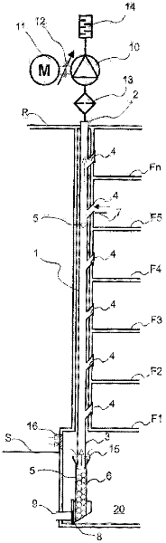
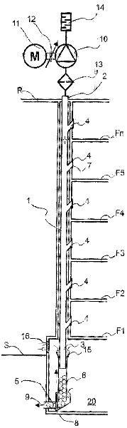
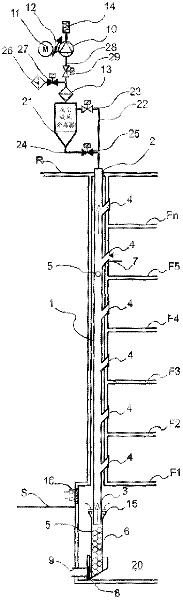
[0028] figure 1 and 2 A simplified and cut-away embodiment of the solution according to the invention is shown. The refuse chute 1 of the material moving system is present in these figures. The refuse chute 1 extends vertically through the floors F1 . . . Fn of the building, in which case the top end 2 of the refuse chute extends eg to the roof R of the building. The bottom end 3 of the refuse chute 1 extends into a space 20 in the bottom of the building, for example a basement. In this figure, the surface of the ground is identified by the letter S. One or more inlet openings 4 are arranged in the refuse chute 1 . The refuse chute 1 in the figures is a section of a pipeline arranged in place in a building.

[0029] The material is fed into the refuse chute via one or more feed holes 4 . The opening means 7 analogously can be connected to the input opening 4 . Furthermore, a valve device V can be connected to the inlet opening, via which valve device the feed of materia...


PUM


Abstract

Method in connection with a refuse chute (1), which refuse chute comprises at least one input aperture (4) of the waste material, in which method the waste material (5) input into the refuse chute from an input aperture (4) is moved in the refuse chute under the effect of gravity to the bottom part of the refuse chute. An opposing air flow with respect to the direction of travel of the waste material (5) is brought about in the refuse chute (1), with which air flow the speed of movement of the waste material is influenced. The invention also relates to an apparatus.

Description

technical field [0001] The invention relates to a method as defined in the preamble of claim 1 . [0002] The invention also relates to a device as defined in the preamble of claim 10 . [0003] The present invention relates generally to material movement systems, such as partial vacuum conveyor systems, and more particularly to the collection and movement of waste materials, such as residential waste. The invention also relates to a refuse chute through which waste is moved by gravity, typically eg from an upper input aperture in a dwelling room, to a lower collection space or corresponding space. Background technique [0004] In systems also known in the prior art waste is moved in the pipeline by means of differential pressure or suction. In these systems, waste material is moved long distances in pipes by suction. Typically for these systems, the differential pressure is created using a partial vacuum device in which a partial vacuum is achieved in the conveying line ...

Claims


Application Information

Patent Timeline
Patent Type & Authority Applications(China)
IPC IPC(8): B65F1/00
CPCB65F1/0093B65F5/005B65G53/58B09B5/00B65F1/00B65F5/00
Inventor G·松德霍尔姆
Owner MARICAP OY
Why Eureka
Try Eureka