Method and arrangement in a pneumatic material conveying system

A conveying system and material technology, applied in the direction of conveyors, transportation and packaging, conveying bulk materials, etc., can solve problems such as blocking openings and difficulties, and achieve the effects of reducing energy demand, fast and effective emptying, and good propulsion effect

Inactive Publication Date: 2011-08-10
MARICAP OY
View PDF9 Cites 4 Cited by
  • Summary
  • Abstract
  • Description
  • Claims
  • Application Information

AI Technical Summary

Problems solved by technology

Tightly packed trash material may partially block valve opening
On the other hand, setting the supplied material to move at the lower part of the supply chute can become difficult

Method used


Image

  • Method and arrangement in a pneumatic material conveying system
  • Method and arrangement in a pneumatic material conveying system
  • Method and arrangement in a pneumatic material conveying system

Examples


Embodiment Construction

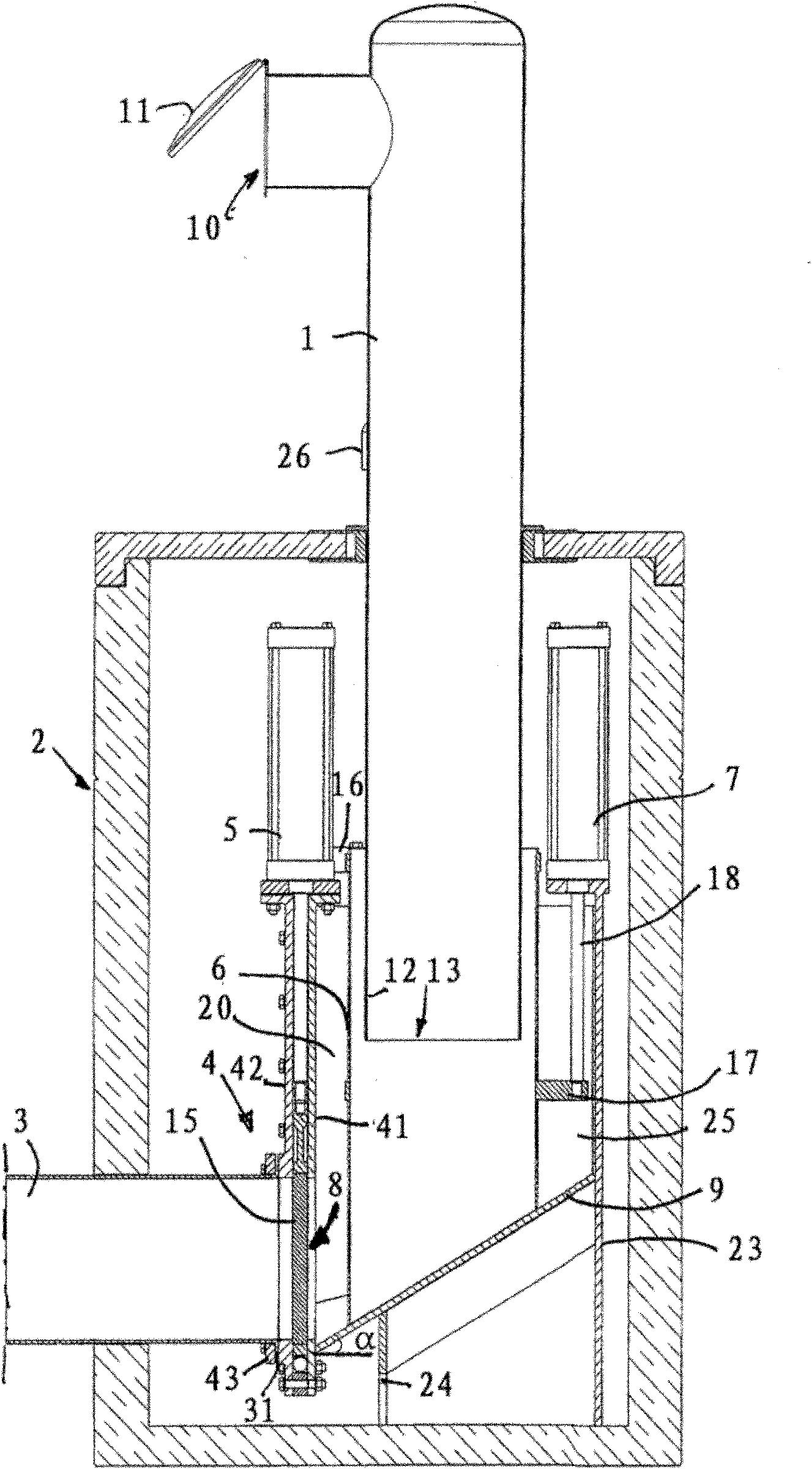
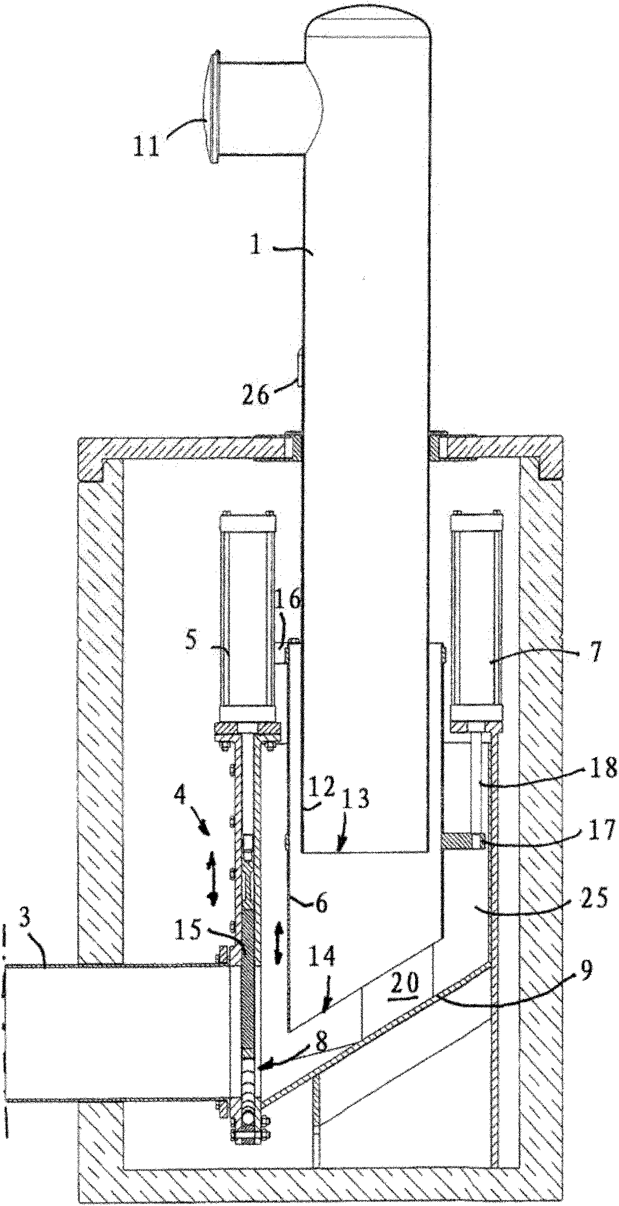
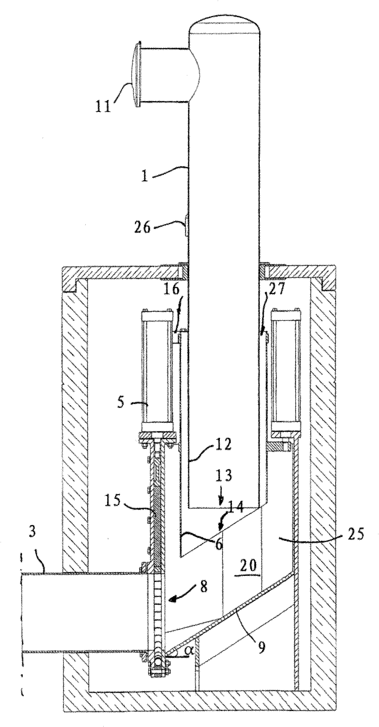
[0018] Figure 1-3 and 5 show a first embodiment of the supply box 2 connected to the feed chute 1 in the material conveying system according to the invention. The supply box 2 comprises a material space 20 which is connected to the delivery pipe 3 . An outlet valve 4 is located between the delivery pipe 3 and the material space 20 of the supply tank 2 , which outlet valve 4 is driven by an actuator 5 . The material space 20 of the feed box is delimited by a wall 25 . At least one feed chute 1 is provided in the supply box material space via the upper part of the material space 20 , through which material is guided into the material space. In the feed chute at least one feed hole 10 is arranged through which material is fed to the feed chute. In the embodiment shown in the figures, a cover 11 is arranged in connection with the feed hole. In the lower part of the material space 20 of the supply box 2 there is an outlet 8 through which the material is conveyed from the suppl...


PUM


Abstract

A method for draining the tank space (20) of a supply tank or feed chute in a pneumatic material conveying system, such as a waste conveying system, of material, such as waste material, in which method the tank space (20) is drained to a conveyor pipe (3) by opening an outlet valve (4), so that the underpressure prevailing in the conveyor pipe, together with the ambient pressure prevailing in the supply tank transfers material from the supply tank to the conveyor pipe (3). In the method, in the supply tank, a wall element (6) positioned at a distance from the outlet aperture (8) of the supply tank and / or from the outlet valve (4), which wall element (6) is arranged to move between at least two positions, i.e. a first position, where the wall element (6) restricts the access of material to the vicinity of the supply tank outlet aperture (8), and a second position, where the wall element (6) does not essentially restrict the access of material to the vicinity of the supply tank outlet aperture (8), is shifted from the first position to the second position. The invention also relates to an arrangement.

Description

technical field [0001] The invention relates to a method according to the preamble of claim 1 . [0002] The invention also relates to a device according to claim 13 . [0003] The present invention generally relates to pneumatic material conveying systems, such as vacuum conveying systems, in particular for collecting and conveying waste, such as household waste. Background technique [0004] There are known systems for conveying waste in pipes by suction. In these systems, waste is transported long distances in pipes by suction. For these systems, the pressure difference is usually obtained with a vacuum device in which a negative pressure is created in the delivery pipe by means of a vacuum generator such as a vacuum pump or ejector device. In the delivery pipe, there is usually at least one valve element, which is opened and closed to regulate the supply of compensation air into the delivery pipe. In these systems, a feed box or feed chute is used at the material sup...

Claims


Application Information

Patent Timeline
Patent Type & Authority Applications(China)
IPC IPC(8): B65G53/46B65G5/00B65G53/24
CPCB65F5/005Y10T137/0402Y10T137/4245B65G53/4691B65F5/00B09B5/00
Inventor G·松德霍尔姆
Owner MARICAP OY
Why Eureka
Try Eureka