Rigidity-adjustable golf club
A golf club and rigid technology, applied in golf balls, golf clubs, rackets, etc., can solve the problem of inability to adjust the rigidity, and achieve the effect of convenient adjustment
- Summary
- Abstract
- Description
- Claims
- Application Information
AI Technical Summary
Problems solved by technology
Method used
Image
Examples
Embodiment 1
[0018] Such as figure 1 , figure 2 , Figure 5 As shown, the present invention is a golf club with adjustable rigidity, comprising a rod body 2 and a club head 1, a handle 3 is arranged on the upper part of the rod body 2, the rod body 2 is a hollow structure, and its inner hole is a large end on the top , a tapered hole with the small end at the bottom, a tapered adjusting rod 6 adapted to it is provided in the inner hole of the rod body, and a lifting mechanism that can drive it to move up and down relative to the tapered hole is provided on the upper end of the adjusting rod 6 , the lower end of the tapered hole is provided with a cylindrical hole 14, the inner wall of the shaped hole is provided with a rubber layer 15, the lower end of the adjusting rod is provided with a cylindrical rod 13, and the cylindrical rod 13 is connected to the inner wall of the cylindrical hole. The rubber layer 15 is a tight fit. The lifting mechanism includes a lifting block 7 fixedly conn...
Embodiment 2
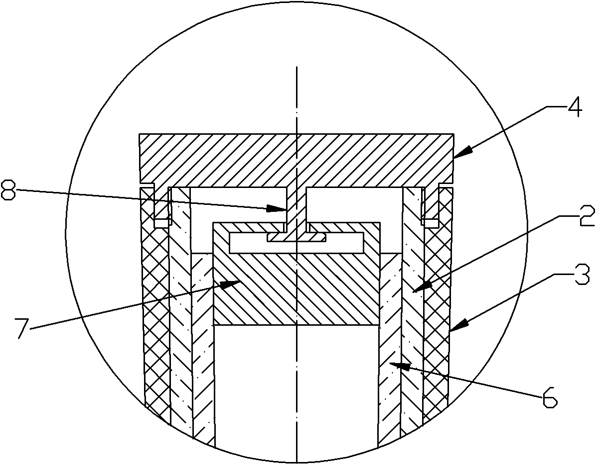
[0020] In the case of Embodiment 1, its described lifting mechanism includes a lifting block 7 fixedly connected with the adjusting rod 6 and an adjusting end sleeve 4 threadedly connected with the rod body, and the center of the adjusting end sleeve 4 is provided with an adjusting column 8. The adjusting column 8 is rotatably connected with the lifting block 7 .
Embodiment 3
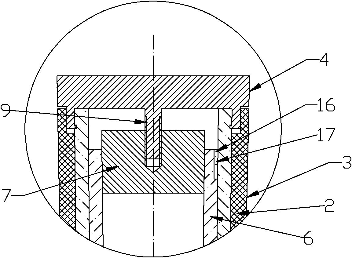
[0022] In the case of Embodiment 1, the lifting mechanism includes a lifting block 7 fixedly connected to the adjusting rod 6 and an adjusting end sleeve 4 connected to the rod body 2. A through hole is arranged in the center of the adjusting end sleeve 4. hole, the center of the lifting block is fixed with an adjusting stud 9, and the adjusting stud 9 passes through the through hole and is connected with an adjusting nut 18.
[0023] When the adjustment rod is at the lowest side, the outer wall of the adjustment rod fits the inner wall of the rod. At this time, the rigidity of the club is the best, and the elastic deformation of bending is most likely to occur when hitting the ball. When the adjustment rod is driven by the lifting mechanism When moving upward relative to the inner hole of the rod, the gap between the outer wall of the adjustment rod and the inner wall of the rod becomes larger and larger, so that when the club hits the ball, the rod body first bends and deform...
PUM
 Abstract
Description
Claims
Application Information
 - R&D
- Intellectual Property
- Life Sciences
- Materials
- Tech Scout
- Unparalleled Data Quality
- Higher Quality Content
- 60% Fewer Hallucinations
Browse by: Latest US Patents, China's latest patents, Technical Efficacy Thesaurus, Application Domain, Technology Topic, Popular Technical Reports.
© 2025 PatSnap. All rights reserved.Legal|Privacy policy|Modern Slavery Act Transparency Statement|Sitemap|About US| Contact US: help@patsnap.com


