
Air cap

An air cap, together technology, applied in the direction of threaded connection, pipe/pipe joint/pipe fitting, engine components, etc., can solve the problems of not using electric control, affecting the precision of flow control, easy to block, etc., to achieve the effect of smooth ventilation

Inactive Publication Date: 2012-07-04
山东沃克控制阀有限公司
View PDF0 Cites 0 Cited by
  • Summary
  • Abstract
  • Description
  • Claims
  • Application Information

AI Technical Summary

Problems solved by technology

[0002] The control of precision control valves can be divided into electric control and pressure control. The precision of electric control is high, but in some flammable and explosive fields, electric control cannot be used. Connected to ensure equal air pressure, the air hole of the pressure control body is easily blocked due to the influence of the use environment, which affects the flow control precision

Method used


Image

  • Air cap
  • Air cap

Examples


Embodiment Construction

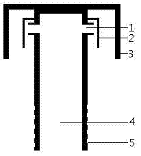
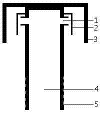
[0009] As shown in the figure, the vent pipe 4 lower end is provided with thread 5, and the top is welded together with the brim of the hat 3, and the vent pipe 4 top is provided with a vent hole 1, and the vent hole 1 outside is provided with a vent hole baffle plate 2.

[0010] During use, the ventilation of the valve body is communicated with the outside world by the vent pipe 4, the vent 1, and the vent baffle plate 2 can prevent the overheated gas inside the valve body from blowing directly to the brim of the hat 3, so that the brim of the hat 3 is overheated or damaged.


PUM


Abstract

The invention provides an air cap, which aims to prevent the problem that vent holes of pressure controlled units are easy to be blocked. A thread is arranged at the lower end of a vent pipe of the air cap, the top end of the vent pipe is welded with a cap edge, vent holes are arranged on the upper portion of the vent pipe, and vent hole baffles are arranged outside the vent holes. The air cap guarantees smoothness in venting effectively, and over-high temperature of gas inside can be avoided, so that affection to detachment of the air cap is avoided during repairing.

Description

technical field [0001] The invention relates to the field of precision control of gas-liquid flow, in particular to a gas cap. Background technique [0002] The control of precision control valves can be divided into electric control and pressure control. The precision of electric control is high, but in some flammable and explosive fields, electric control cannot be used. In order to ensure equal air pressure, the vent hole of the pressure control body is easily blocked due to the influence of the use environment, which affects the precision of flow control. Contents of the invention [0003] In order to prevent the problem that the air hole of the pressure control body is easily blocked, the invention provides an air cap. [0004] The present invention is achieved in that the lower end of the ventilation pipe is provided with threads, the top is welded together with the visor of the hat, the upper part of the ventilation pipe is provided with a ventilation hole, and a v...

Claims


Application Information

Patent Timeline
IPC IPC(8): F16K51/00F16L15/00
Inventor 王秀孙刚王宏刘业军刘常成刘晓丽
Owner 山东沃克控制阀有限公司
Learn More