Static deduster and step-by-step rapping deashing method thereof

An electrostatic precipitator and ash cleaning technology, applied in electrostatic separation, electrode cleaning and other directions, can solve the problems of increasing dust concentration at the outlet of electrostatic precipitator, inaccurate setting of ash cleaning and rapping plan, and large amount of secondary dust. Achieve the effect of reducing the total amount of secondary dust, reducing the total amount of secondary dust, and reducing the concentration of outlet dust

Active Publication Date: 2012-07-11
CHINA POWER INVESTMENT CORPORATION +1
View PDF3 Cites 8 Cited by
  • Summary
  • Abstract
  • Description
  • Claims
  • Application Information

AI Technical Summary

Problems solved by technology

[0003] However, because the existing electrostatic precipitator is generally equipped with a cathode line rapping and cleaning device and an anode plate rapping and cleaning device in each electric field, a rapping and cleaning device completes the cleaning of all anode plates or cathode lines in an electric field. Vibration and dust removal work lead to a large amount of secondary dust generated in the electric field. At the same time, in the actual ope

Method used


Image

  • Static deduster and step-by-step rapping deashing method thereof
  • Static deduster and step-by-step rapping deashing method thereof

Examples


Embodiment Construction

[0015] Hereinafter, preferred embodiments of the present invention will be described in detail with reference to the accompanying drawings.

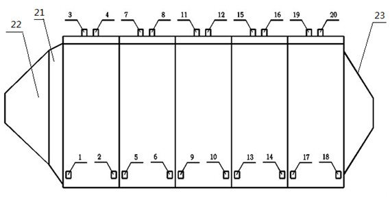
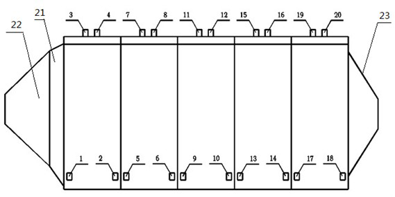
[0016] figure 1 It is a structural schematic diagram of the electrostatic precipitator of the present invention. As shown in the figure, the electrostatic precipitator of the present invention includes a casing 21, and the two ends of the casing 21 are respectively provided with an air inlet 22 and an exhaust port 23. There are five electric fields composed of cathode wires and anode plates in the casing 21 (from left to right in the figure are the first, second, third, fourth, and fifth electric fields), and two cathodes are arranged in each electric field Line vibration cleaning device and two anode plate vibration cleaning devices.

[0017] In this embodiment, the cathode line rapping and cleaning devices in each electric field are respectively located on the left and right sides of the cathode line (in the figure, 3, 7, 11, 15, 19 a...


PUM


Abstract

The invention which discloses a static deduster and a step-by-step rapping deashing method thereof belongs to the technical field of static dedusting. The static deduster of the invention comprises a casing, two ends of the casing are provided with an air inlet and an air outlet respectively, at least one electric field comprising a cathode wire and an anode plate which cooperate with each other is arranged in the casing, and at least two cathode wire rapping deashing devices and at least two anode plate rapping deashing devices are arranged in each electric field. According to the step-by-step rapping deashing method of the static deduster of the invention, all the cathode wire rapping deashing devices and all the anode plate rapping deashing devices run in different periods of time. According to the invention, the total amount of re-entrainment generated during rapping deashing is reduced, and the concentration of dust on the outlet of the static deduster is reduced.

Description

technical field [0001] The invention belongs to the technical field of electrostatic dust removal, and in particular relates to an electrostatic dust collector and a step-by-step vibration cleaning method thereof. Background technique [0002] The existing electrostatic precipitator includes a casing, the two ends of the casing are respectively provided with an air inlet and an exhaust port, and several electric fields composed of cathode wires and anode plates are arranged in the casing, and vibration cleaning is arranged in the electric field. The device; the gas passes through the cathode line and the anode plate in parallel, and a negative high-voltage direct current is applied to the cathode line to make the ionized gas generate negative ions. It falls off from the surface of the electrode, so as to achieve the purpose of cleaning the dust of the dust collector. [0003] However, because the existing electrostatic precipitator is generally equipped with a cathode line...

Claims


Application Information

Patent Timeline
IPC IPC(8): B03C3/76
Inventor 原钢刘艺
Owner CHINA POWER INVESTMENT CORPORATION
Why Eureka
Try Eureka