Stability monitoring system and stability monitoring method of lifting equipment

A lifting equipment and monitoring system technology, applied in cranes and other directions, can solve the problems that affect the stability of the lifting equipment, the monitoring of the stability is not real, and the crane cannot be prevented from tipping over.

Active Publication Date: 2012-07-11
SANY AUTOMOBILE HOISTING MACHINERY
View PDF6 Cites 33 Cited by
  • Summary
  • Abstract
  • Description
  • Claims
  • Application Information

AI Technical Summary

Problems solved by technology

[0005] 1. The moment limiter method can only prevent the crane from tipping over due to overload, but cannot prevent the crane from tipping due to factors such as uneven support, internal leakage of the oil cylinder, subsidence of the foundation, oblique hanging, wind load, etc.;
[0006] 2. The load transfer rate method cannot accurately judge the reaction force of each outrigger, but can only predict the danger of crane rollover;
[0007] 3. Crane leveling is a prerequisite for stability monitoring. Neither the torque limiter method nor the load transfer rate method takes this prerequisite into account, so the stability monitoring is not true. The traditional method uses a bubble level to level For cranes, due to manufacturing and installation accuracy and human factors, the crane cannot be truly leveled. Even if it is leveled, there may be outriggers with empty legs, which will affect the stability of the lifting equipment.

Method used


Image

  • Stability monitoring system and stability monitoring method of lifting equipment
  • Stability monitoring system and stability monitoring method of lifting equipment
  • Stability monitoring system and stability monitoring method of lifting equipment

Examples


Embodiment Construction

[0037] In order to understand the above-mentioned purpose, features and advantages of the present invention more clearly, the present invention will be further described in detail below in conjunction with the accompanying drawings and specific embodiments.

[0038] In the following description, many specific details are set forth in order to fully understand the present invention, but the present invention can also be implemented in other ways different from those described here, therefore, the present invention is not limited to the specific embodiments disclosed below limit.

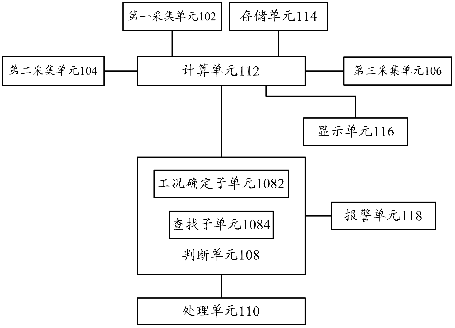
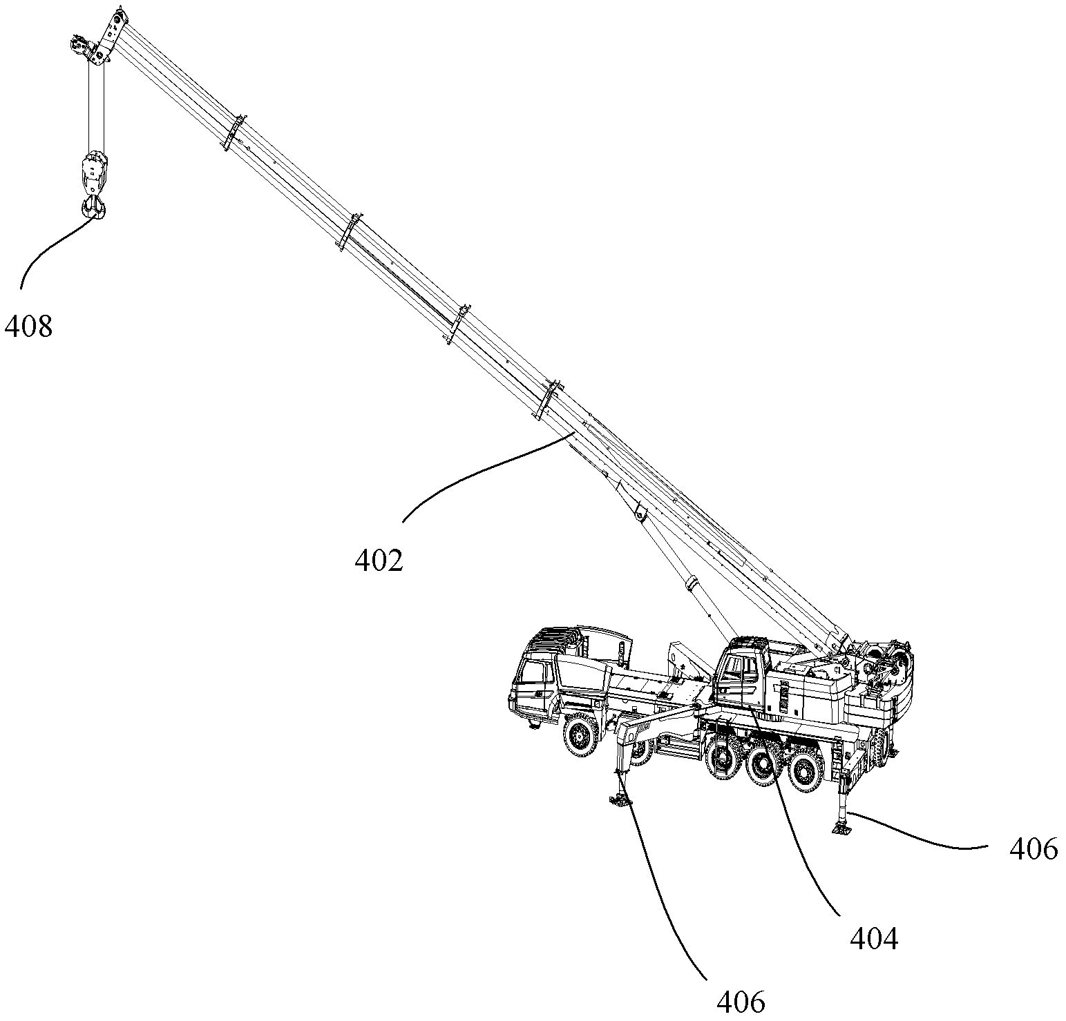
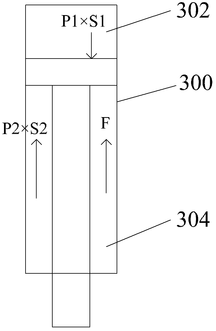
[0039] First please refer to Figure 1 to Figure 3 , detailing the lifting equipment stability monitoring system according to the present invention.

[0040] figure 1 A block diagram of the stability monitoring system for lifting equipment is shown. Such as figure 1 As shown, the lifting equipment stability monitoring system according to the embodiment of the present invention includes: a first ac...


PUM


Abstract

The invention provides a stability monitoring system of lifting equipment, comprising a first acquisition unit which is arranged at the position of a landing leg oil cylinder of the lifting equipment and acquires the force applied to each landing leg, a second acquisition unit which acquires the lifting weight of the lifting equipment, a judging unit which reads a working condition table which ispre-stored in a storage unit and a processing unit, wherein the working condition table contains working condition information, a lifting weight parameter and a rated landing leg counter-force, the working condition information corresponds to the lifting weight parameter and the rated landing leg counter-force one by one, the judging unit finds the rated landing leg counter-force which corresponds to the obtained lifting weight from the working condition table and compares the rated landing leg counter-force with the acquired force applied to each landing leg, and the processing unit limits the action of a corresponding executing mechanism according to the judging result. In the technical scheme of the invention, the stability monitoring system can detect the counter-force applied to eachlanding leg in real time and the rotating position of each landing leg, compares with the preset working condition table, controls the action of a crane and avoids the roll-over of the crane. The invention also provides a stability monitoring method of lifting equipment.

Description

technical field [0001] The invention relates to the technical field of construction machinery, in particular to a lifting equipment stability monitoring system and a method thereof. Background technique [0002] The outriggers of the crane need to be opened before the construction operation to obtain a stable working state, and the stability is an important indicator of the safety performance of the crane. At present, the stability of the crane can be monitored by using a moment limiter, that is, when overloaded by a certain multiple, The moment limiter sends out an alarm message and limits the movement of the crane in a dangerous direction. [0003] Another way is to detect the reaction force of each leg of the crane in real time, according to the formula to calculate the load transfer rate (where, F 1 is the reaction force of one outrigger, F 2 is the reaction force of the outrigger on the other side), if the load transfer rate is greater than 0.8, it is confirmed that...

Claims


Application Information

Patent Timeline
Patent Type & Authority Applications(China)
IPC IPC(8): B66C23/88B66C23/94
Inventor 段春玲万钦向峰
Owner SANY AUTOMOBILE HOISTING MACHINERY
Why Eureka
Try Eureka