Quenching recovery test system for resistance-type superconducting current limiter

A superconducting current limiter, recovery testing technology, applied in the direction of measuring resistance/reactance/impedance, instruments, measuring devices, etc., can solve the problems of low withstand voltage, large interference of data acquisition cards, limited working conditions, etc. The effect of fast speed, ensuring grid security and ensuring equipment security

Inactive Publication Date: 2020-06-12
TSINGHUA UNIV +1
View PDF11 Cites 1 Cited by
  • Summary
  • Abstract
  • Description
  • Claims
  • Application Information

AI Technical Summary

Problems solved by technology

[0008] (1) Under high voltage conditions, the current source and acquisition card connected to the system may be at risk of being broken down by high voltage; under strong electromagnetic interference, the data acquisition card is greatly disturbed, and the specific voltage value cannot be accurately measured
This makes in-line measurements under high pressure impossible
[0009] (2) During the measurement of the quench recovery process, the recovery time of the superconducting current limiter is very short, and conventional methods make it difficult to measure and observe the recovery process
However, the working conditions of the measurement system are limited, the withstand voltage is low, the system is relatively simple, and online detection cannot be realized

Method used


Image

  • Quenching recovery test system for resistance-type superconducting current limiter
  • Quenching recovery test system for resistance-type superconducting current limiter
  • Quenching recovery test system for resistance-type superconducting current limiter

Examples


Embodiment Construction

[0031] In order to make the object, technical solution and advantages of the present invention clearer, the present invention will be further described in detail below in conjunction with the accompanying drawings and embodiments. It should be understood that the specific embodiments described here are only used to explain the present invention, and do not limit the protection scope of the present invention.

[0032] In order to better understand the present invention, an application example of a quench recovery test system for a resistive superconducting current limiter proposed by the present invention will be described in detail below.

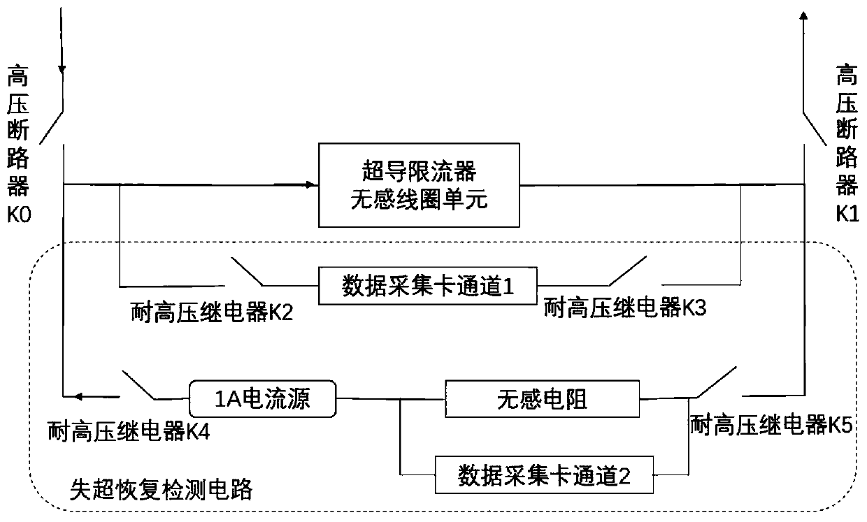
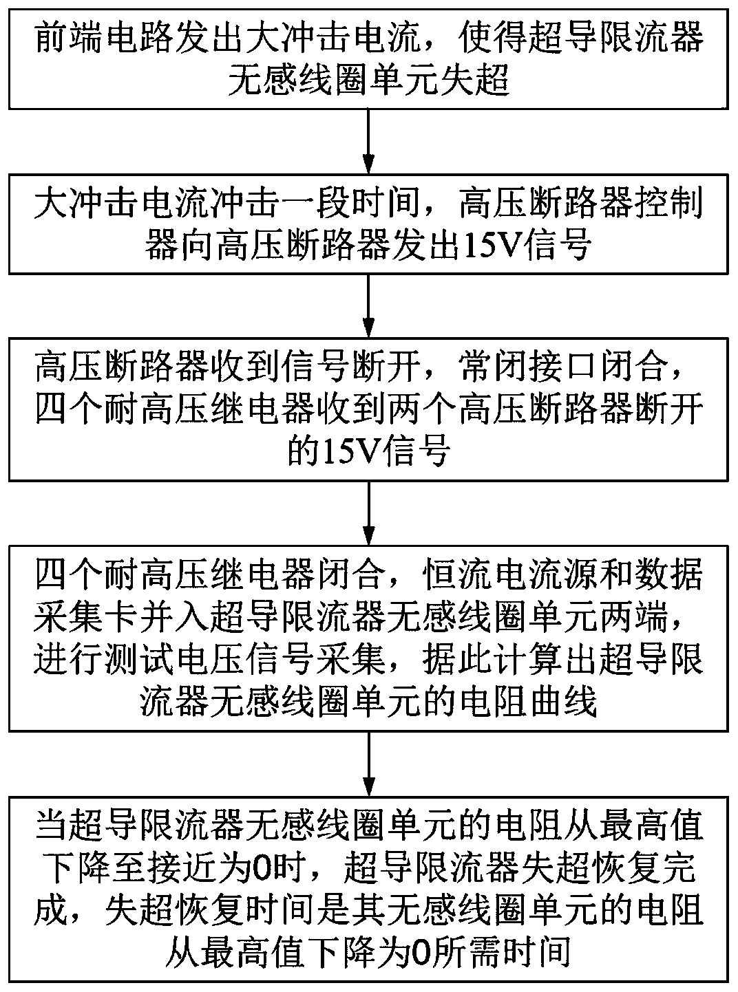
[0033] In order to solve the problem of quench recovery testing of the current resistive superconducting current limiter under AC high voltage conditions, it is necessary to ensure the safety of the equipment and the accuracy of measurement at the same time, and the quench recovery of the resistive superconducting current limiter of the pres...


PUM


Abstract

The invention provides a quenching recovery test system for a resistance-type superconducting current limiter, which comprises a to-be-superconducting current limiter non-inductive coil unit, two circuit breakers, four relays, a controller, a constant current source, a non-inductive resistor and a data acquisition card with multiple channels, two ends of the superconducting current limiter non-inductive coil unit are respectively connected with each circuit breaker. A data acquisition card channel 1 is connected in parallel to two ends of the superconducting current limiter non-inductive coilunit through two relays which are connected in series. Two ends of a branch formed by connecting the constant current source and the non-inductive resistor in series are respectively connected to twoends of the non-inductive coil unit of the superconducting current limiter in parallel through another two relays, and a data acquisition card channel 2 is connected to two ends of the non-inductive resistor in parallel; and the controller detects that each circuit breaker sends out a high-level pulse signal at the same time, then controls each relay to be completely closed, and controls the controller and each relay to be completely reset within a set time. According to the invention, the rapid and accurate test of the quench recovery time of the resistance-type superconducting current limiter can be realized under an alternating-current high-voltage condition.

Description

technical field [0001] The invention relates to the field of a resistance type superconducting current limiter and a superconducting magnet, in particular to a quench recovery test system for a resistance type superconducting current limiter. Background technique [0002] Quench and quench propagation: A superconducting magnet is a magnetic field generating device wound with a superconducting wire strip. Under the action of mechanical vibration, thermal load, current, external magnetic field and other conditions, an overheated area will appear inside the superconducting magnet, that is, No longer exhibit superconducting properties, this phenomenon is called quenching. When the local input energy exceeds a certain threshold, the normal region will experience instability expansion, resulting in a large amount of loss in the superconducting magnet. This phenomenon is called quench propagation. [0003] The application of superconducting technology in power grid is an important...

Claims


Application Information

Patent Timeline
IPC IPC(8): G01R27/00
CPCG01R27/00
Inventor 姜豪瞿体明韦德福朱义东王帅燕宇帆宋彭
Owner TSINGHUA UNIV
Why Eureka
Try Eureka