Improved magnetic energy water-saving toilet stool

A toilet, magnetic energy technology, applied in flushing toilets, water supply devices, flushing equipment with water tanks, etc., can solve the problems of insufficient suction, unusable toilets, loud noise, etc., to reduce odor, improve toilet environment, flush clean effect

Active Publication Date: 2013-11-06
温门生
View PDF7 Cites 0 Cited by
  • Summary
  • Abstract
  • Description
  • Claims
  • Application Information

AI Technical Summary

Problems solved by technology

Although the water-saving closet of this patent reaches the purpose of saving water and effectively preventing odor from overflowing, this water-saving closet has three shortcomings. The one is that when the sealing cover is closed, the sealing cover collides with the exit wall of the toilet pit, and the sound is very loud, and The impact will affect the durability of the sealing cover and the exit of the toilet pit; second, when the sealing cover is not opened for normal flushing, the sealing cover cannot automatically replenish the water seal; third, if the magnets on both sides of the rear end of the sealing cover demagnetize, causing suction When it is not enough, the magnetic force cannot be adjusted externally, which will cause the toilet to be unusable and bring worries to the user

Method used


Image

  • Improved magnetic energy water-saving toilet stool
  • Improved magnetic energy water-saving toilet stool
  • Improved magnetic energy water-saving toilet stool

Examples


Embodiment 1

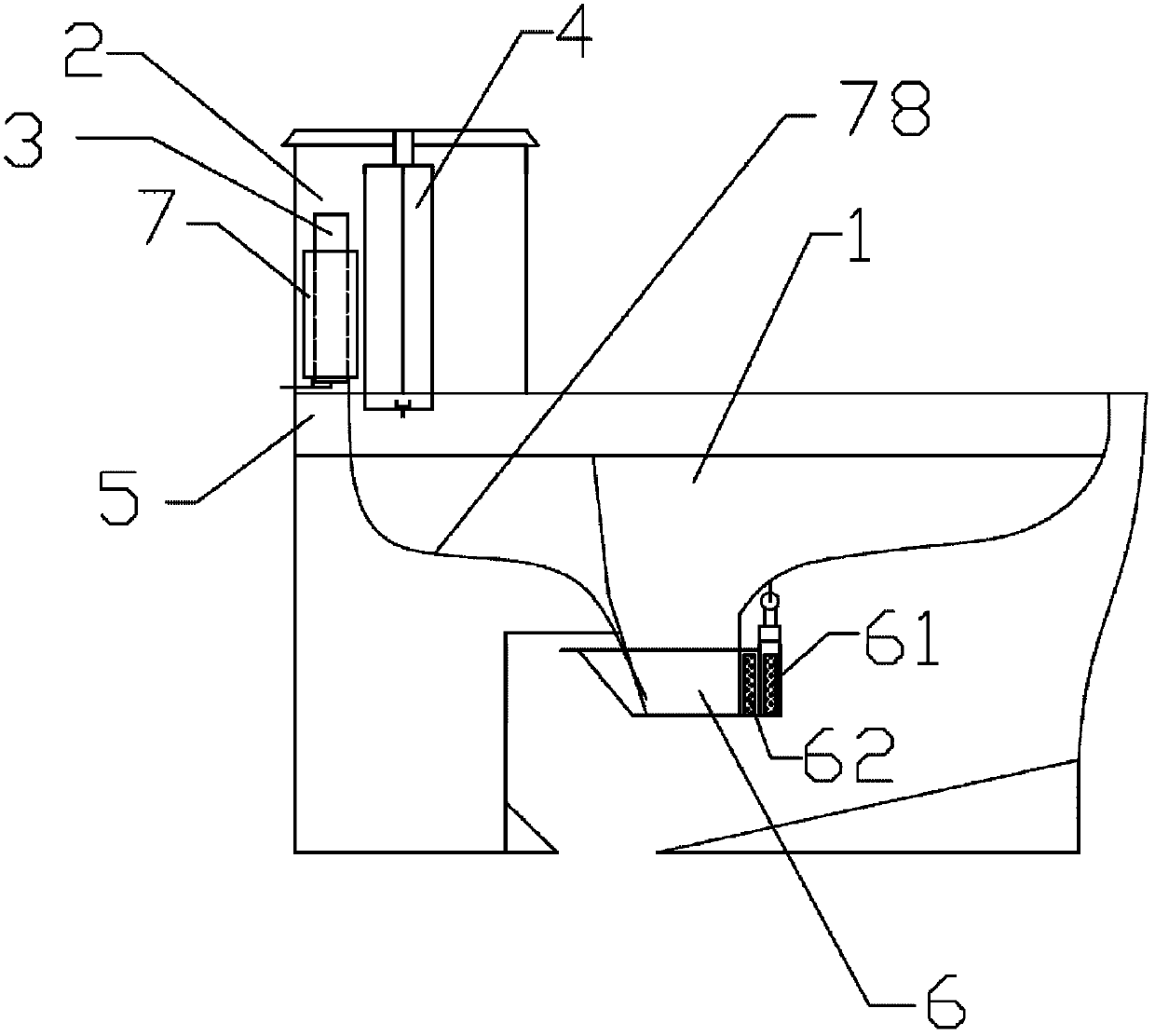
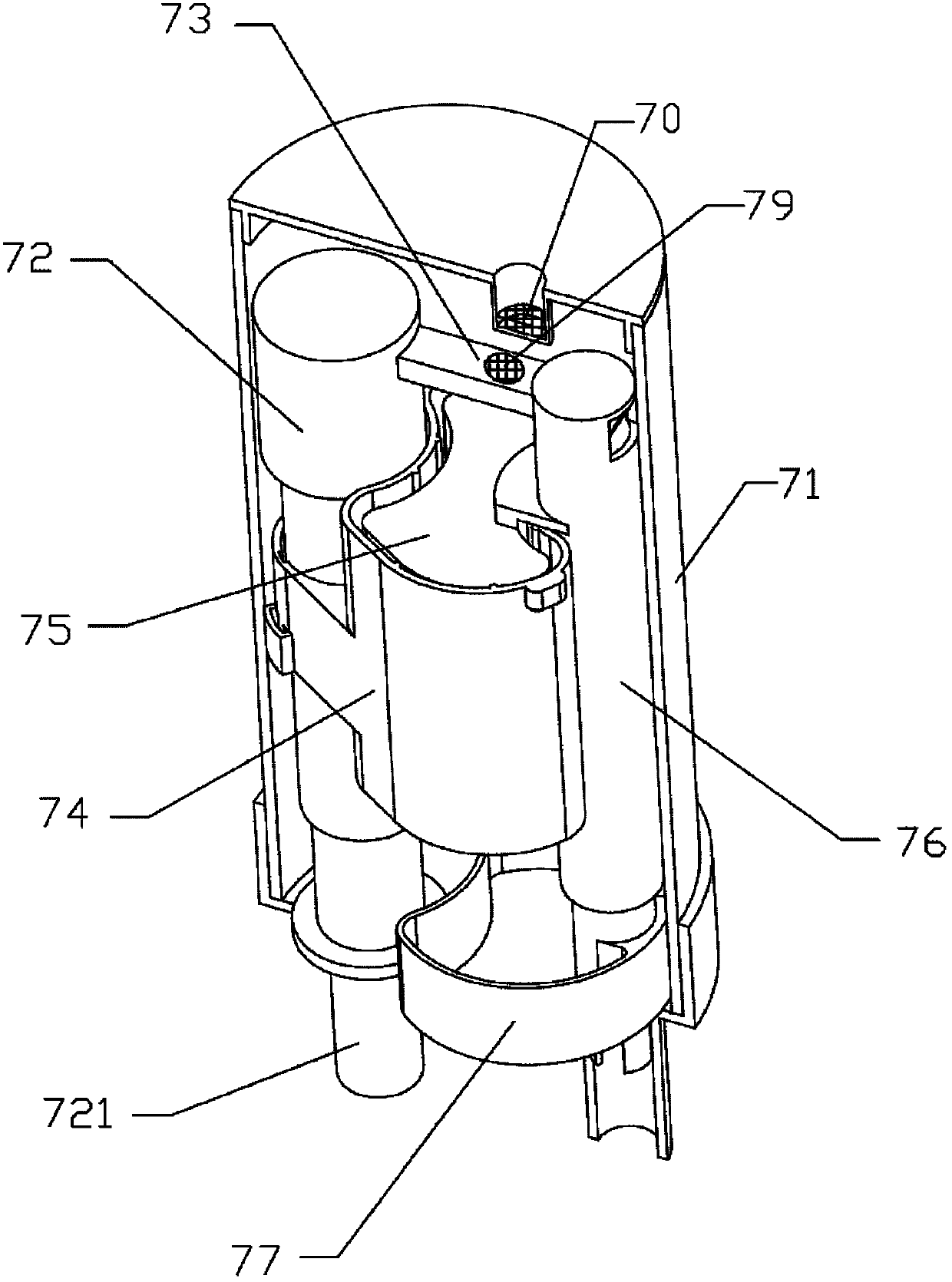
[0025] Such as figure 1 , figure 2 , image 3 with Figure 4 As shown, the improved magnetic energy water-saving closet of the present embodiment includes a toilet pit 1, a water tank 2 is arranged behind the toilet pit 1, a water inlet valve 3 and a drain valve 4 are respectively arranged on the left and right sides of the water tank, and a drain valve 4 is provided below the drain valve 4. There is a flushing tank 5, which is connected to the toilet pit 1, and a sealing cover 6 is arranged at the exit of the toilet pit 1. A magnet A61 is installed, and a magnet B62 of the opposite sex is installed on the outer wall of the toilet pit outlet in front of the rear wall of the sealing cover 6 corresponding to the magnet A. A water replenishing device 7 is also provided in the water tank 2, which is located at the water inlet. In front of the valve 3, the water replenishing device 7 includes a water storage tank 71, the bottom surface of the water storage tank 71 is provided ...

Embodiment 2

[0027] Such as figure 1 , figure 2 , image 3 , Figure 4 , Figure 5 , Image 6 with Figure 7-1 , 7-2 As shown, the present embodiment is basically the same as Embodiment 1, except that a dividing plate 10 is provided on the outer wall of the toilet pit outlet above the sealing cover 6 front ends, and a magnet E81 is fixed at the sealing cover 6 front ends, and on the dividing plate 10 and the sealing cover A cylinder 82 is fixed at the corresponding position of the magnet E81 at the front end, and an adjustment rod 83 is arranged inside the cylinder 82. The adjustment rod 83 extends out of the upper layer of the partition 10. A magnet F84 that attracts oppositely to the magnet E81 is fixed on one end close to the magnet E81, thereby forming the adjusting device 8 . In this way, the adjusting rod 83 can be rotated up and down by the screw thread, thereby adjusting the distance between the magnet E81 and the magnet F84, and then adjusting the magnetic force, so as to...

Embodiment 3

[0030] Such as figure 1 , figure 2 , image 3 , Figure 4 , Figure 5 , Image 6 with Figure 8 As shown, this embodiment is basically the same as Embodiment 2, except that the structure of the buffer device 8 is somewhat different. A magnetic piece G922 is also provided in the outer sleeve 91 above the head of the buffer push rod 92, and the magnetic piece G922 The diameter of the outer sleeve 91 coincides with the inner diameter of the outer sleeve 91, so that the magnetic sheet G922 can only move up and down in the outer sleeve 91, but cannot be turned over. The middle part of the magnetic sheet G922 has a hole, and the magnetic sheet G922 is also provided with a hole that can cover the hole The cover sheet 923 is fixed with a magnet H921 at the upper end of the buffer push rod 92, and the magnet sheet G922 and the magnet H921 are homosexually repelled and placed.


PUM


Abstract

The invention discloses an improved magnetic energy water-saving toilet stool comprising a water tank, wherein a water replenishing device is arranged in the water tank and comprises a water storage tank; a water inlet hole and a water outlet hole are arranged on the bottom surface of the water storage tank; the water storage tank is internally provided with a water inlet valve for the water tank of the stool; the water inlet valve for the water tank of the stool comprises a water inlet tube, a connecting rod switch, an outer float sleeve cup, an inner float sleeve cup and a stay tube; a water inlet of the water inlet tube penetrates through the water inlet hole to be externally connected with a water source; an exhaust tube is arranged in the middle of the stay tube; an opening at one end of the exhaust tube is located at the upper part of the stay tube, and an opening at the other end of the exhaust tube is located at the lower end of the stay tube; the lower end of the stay tube is inserted into the water outlet hole; the lower end wall of the stay tube is provided with a notch; the stay tube above the notch is fixedly connected with a water holding tray; the position of the bottom surface of the water holding tray, corresponding to the water outlet hole, is provided with a seal ring used for closing the water outlet hole; the water outlet hole is further connected with a water replenishing guide tube; the other end of the water replenishing guide tube extends into a seal closure; the top end of the stay tube or the connecting rod switch is provided with a magnet C; and a panel on the top surface of the water storage tank, corresponding to the magnet C in position, is fixed with a magnet D attracting the magnet C.

Description

technical field [0001] The invention relates to a water-saving closet installed in a toilet, in particular to an improved magnetic energy water-saving closet. Background technique [0002] Now there are all kinds of toilets on the market, with various shapes and dazzling arrays. According to its function, it can be divided into sitting type, squatting type, or toilet with or without a water tank, or a toilet with two flushing switches for defecation and defecation according to the size of the water. The common points of above-mentioned all kinds of closets are: the one, adopt the water trap to make the sealing anti-odor part of closet; pressure device. But there are many deficiencies in the above-mentioned closet, one is that the water consumption for flushing the toilet is large, and the bent water pipe of the closet makes the water volume and the water pressure for flushing the toilet all large, otherwise it will not be flushed clean, and blockage will easily occur durin...

Claims


Application Information

Patent Timeline
Patent Type & Authority Patents(China)
IPC IPC(8): E03D11/10E03D5/012
Inventor 温门生
Owner 温门生
Why Eureka
Try Eureka