Transmission gear of tube mill

A transmission device and tube mill technology, applied in the direction of transmission device, transmission device parts, gear transmission device, etc., can solve the problems of large maintenance workload, high operation failure rate, large size of reducer, etc., and achieve short installation period, The effect of less capital investment and weight reduction

Active Publication Date: 2012-07-11
JIANGSU JINXIANG TRANSMISSION EQUIP
View PDF4 Cites 7 Cited by
  • Summary
  • Abstract
  • Description
  • Claims
  • Application Information

AI Technical Summary

Problems solved by technology

The edge transmission has the characteristics of compact layout and low price, but the transmission efficiency is low, the maintenance workload is large, and the operation failure rate is high
The central transmission has the advantages of high transmission efficiency, safety and reliability, and is favored by users. However, the reducer is large in size and expensive. At present, the central transmission reducer with a transmission power of more than 4500kW does not have the processing and manufacturing capabilities and needs to be imported from abroad.

Method used


Image

  • Transmission gear of tube mill
  • Transmission gear of tube mill

Examples


Embodiment Construction

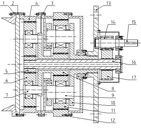
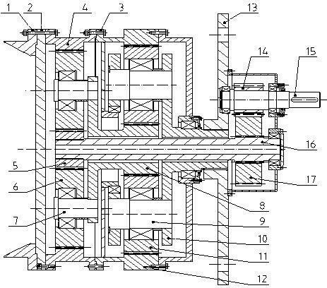
[0020] Such as figure 1 As shown, the transmission device is a first-stage parallel gear reduction + a second-stage planetary gear reduction; the input shaft 15 is installed on the torque frame 13, and the input gear 14 on the input shaft 15 meshes with the input mating gear 17, and the input gear 14 and the input mating gear 17 The first-stage parallel gear reduction is completed; the flexible hollow shaft 16 is installed in the center of the connecting box 3, the input mating gear 17 and the flexible hollow shaft 16 are connected by splines, and the flexible hollow shaft 16 is rigid to the second-stage sun gear 5 Combined together, the second-stage planetary gear 6 on the second-stage planetary shaft 7 meshes with the second-stage sun gear 5, and the second-stage internal ring gear 4 is installed between the coupling box 3 and the flange 2 of the reducer box. The second-stage planetary gear 6 drives the second-stage ring gear 4 to complete the second-stage planetary gear red...


PUM


Abstract

The invention discloses a transmission gear of a tube mill. An input shaft (15) is arranged on a torsion frame (13); an input mating gear (17) is engaged with an input gear (14) on the input shaft (15); a flexible hollow shaft (16) is arranged at the centre of a join box body (3); the input mating gear (17) and a secondary sun wheel (5) are arranged on the flexible hollow shaft (16); a secondary planetary wheel (6) on a secondary planetary wheel shaft (7) is engaged with the secondary sun wheel (5); a secondary inner gear ring (4) is arranged on the join box body (3); the secondary planetary wheel shaft (7) is connected with a tertiary sun wheel (8); a tertiary planetary wheel shaft (9) is arranged on a tertiary planetary frame (10) on the torsion frame (13); a tertiary planetary wheel (11) on the tertiary planetary wheel shaft (9) is engaged with the tertiary sun wheel (8); and a tertiary inner gear ring (12) is connected on the join box body (3). The transmission gear is of fully enclosed structure and is connected by flanges, the installation is easy, and the installation period is short.

Description

technical field [0001] The invention relates to a transmission device, in particular to a transmission device of a tube mill. Background technique [0002] As we all know, in the dry process cement production line, the transmission device of the tube mill mainly includes center transmission and edge transmission. The edge transmission has the characteristics of compact layout and low price, but the transmission efficiency is low, the maintenance workload is large, and the operation failure rate is high. The central transmission has the advantages of high transmission efficiency, safety and reliability, and is favored by users. However, the reducer is large in size and expensive. At present, the central transmission reducer with a transmission power of more than 4500kW does not have the processing and manufacturing capabilities and needs to be imported from abroad. In the past two decades, with the continuous progress of cement production technology, the level of cement indu...

Claims


Application Information

Patent Timeline
Patent Type & Authority Applications(China)
IPC IPC(8): F16H1/28F16H57/023F16H57/08B02C17/24
Inventor 任汉友董建峰刘虎王昆周军吴宏登曹海军杨昕
Owner JIANGSU JINXIANG TRANSMISSION EQUIP
Why Eureka
Try Eureka