Motor vehicle exhaust telemetering system

A technology of telemetry system and motor vehicle, which is applied to the traffic control system, traffic control system, measuring device and other directions of road vehicles, can solve the problems of time-consuming and complicated operation, cumbersome dimming and high cost, and achieves simple on-site installation and wide applicability. , the effect of low cost

Pending Publication Date: 2018-06-12
HANGZHOU YINNUOWEI NEW TECH CO LTD
View PDF8 Cites 5 Cited by
  • Summary
  • Abstract
  • Description
  • Claims
  • Application Information

AI Technical Summary

Problems solved by technology

[0003] The prior art disclosures all adopt two modules to detect automobile exhaust (CH, CO, CO2 and NO). For example, the patent US005319199 adopts the NDIR (non-dispersive infrared) module to measure CO, CO2 and CH, and uses the ultraviolet module to detect NOx; Patent CN 1260571 C uses a laser module to measure CO and CO2, and an ultraviolet module to measure HC and NO; the scheme of two modules is used, the integrated system is relatively large, and two sets of optical path systems are used, which is costly; at the same time, the light adjustment is cumbersome during on-site installation ; In addition, each module needs to be calibrated before the test, which is time-consuming and complicated

Method used


Image

  • Motor vehicle exhaust telemetering system
  • Motor vehicle exhaust telemetering system
  • Motor vehicle exhaust telemetering system

Examples


Embodiment 1

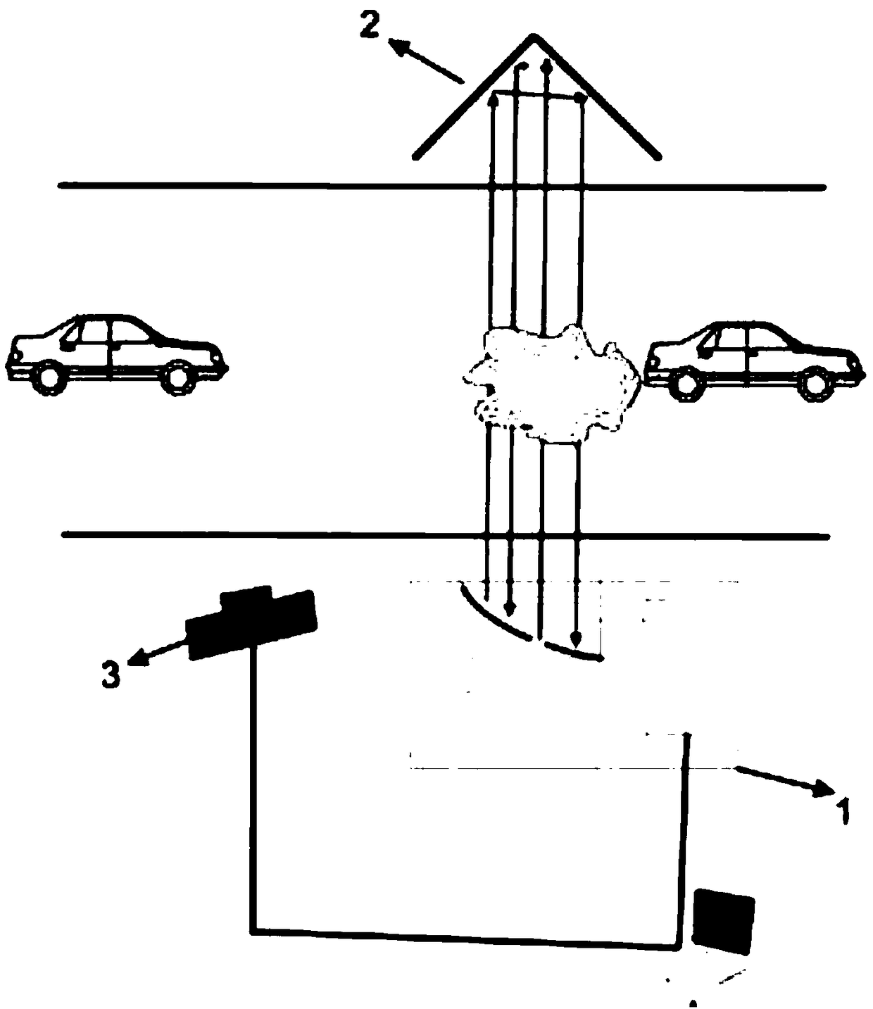
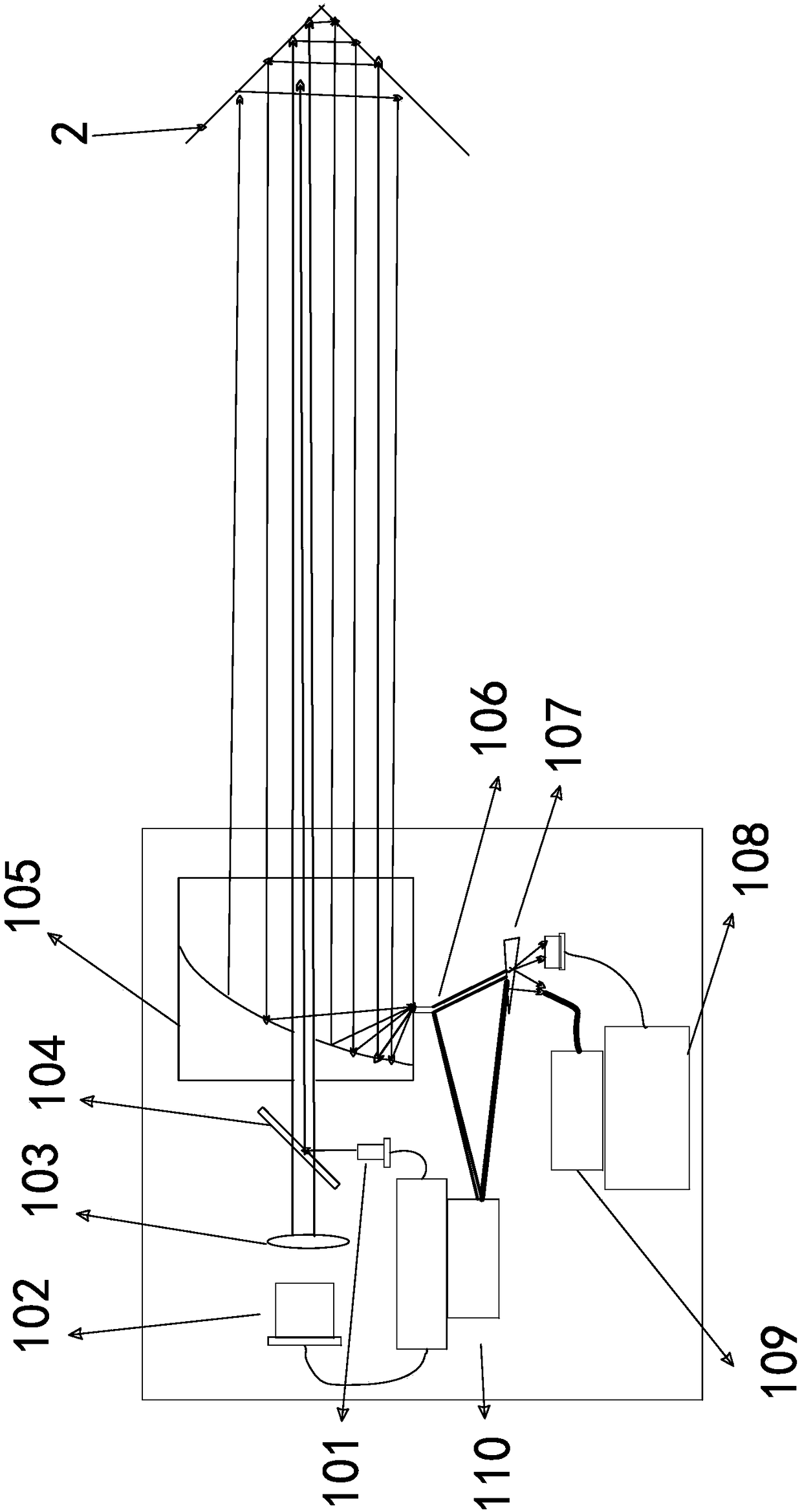
[0027] refer to figure 1 , figure 1 An embodiment of the present invention is shown, a motor vehicle exhaust remote measurement system, including a telemetry host 1 arranged on one side of the road and an optical reflection unit arranged on the other side of the road, the optical reflection unit can be a corner reflector 2 or a pyramid Angular, the telemetry host 1 further includes:

[0028] A detection light emission unit, the detection light emission unit includes a laser emission module 102 and an ultraviolet emission module 110, wherein the wavelength of the laser light emitted by the laser emission module 102 covers the absorption lines of CH and NO, and the wavelength of ultraviolet light emitted by the ultraviolet emission module 110 Covers the absorption lines of CO and CO2;

[0029] A detection unit, the detection unit comprises an off-axis parabolic mirror 105 and a Y-shaped optical fiber 106 for transmitting detection light, the off-axis parabolic mirror 105 and a...

Embodiment 2

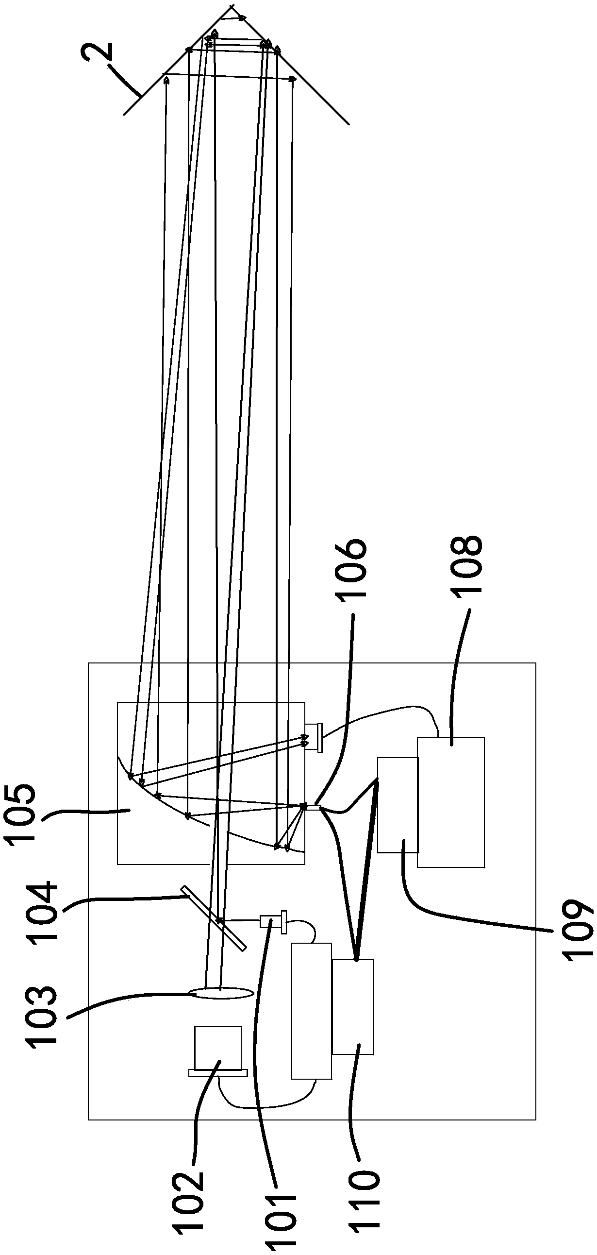
[0039] refer to figure 2 , figure 2Another embodiment of the present invention is shown. The difference between this embodiment and Embodiment 1 is that in this embodiment, the collimated laser light and the collimated ultraviolet light in the measurement cell are not parallel, for example, in a four-meter-wide On the road, the stagger angle between the collimated laser light and the collimated UV light is between -0.5° and 0.5°. The collimated laser light returns to one focal point through the off-axis parabolic mirror 105, and the collimated ultraviolet light returns to the other focal point through the off-axis parabolic mirror 105, and the return light of the two is separated. Therefore, compared with the first embodiment, this embodiment does not need to separate the returned light, and directly receives the laser light through the photodetector 108 and receives the ultraviolet light through the spectrometer 109 .


PUM


Abstract

The invention provides a motor vehicle exhaust telemetering system, and belongs to atmospheric pollution source monitoring equipment. The problems that tail gas of an existing motor vehicle is difficult to monitor, the detection range of the monitoring equipment is small, arrangement is troublesome, and debugging is complicated are solved. The motor vehicle exhaust telemetering system is providedwith a laser emission module and an ultraviolet emission module, data of CH, NO, CO and CO2 can be monitored simultaneously, and the monitoring range is wide; meanwhile, an integrated measuring cell which is constituted by a telemetering host and an optical reflecting unit is adopted as a monitoring point, arrangement is simple, and during debugging, what is needed is to simply debug the optical reflecting unit.

Description

technical field [0001] The invention relates to the field of exhaust remote measurement, in particular to a motor vehicle exhaust remote measurement system. Background technique [0002] Motor vehicle exhaust pollution has become an important factor affecting the air quality of my country's cities. With the continuous increase in the number of motor vehicles and the release of the policy of exempting the exhaust of new vehicles within six years, the remote sensing detection technology of motor vehicle exhaust has become the key to improving the supervision and efficiency of vehicle exhaust emissions. important means. The "Law of the People's Republic of China on the Prevention and Control of Atmospheric Pollutants" clearly stipulates that starting from January 1, 2016, real-time exhaust remote sensing detection of motor vehicles on the road can be carried out without affecting traffic. In recent years, various localities have successively promulgated local standards for remo...

Claims


Application Information

Patent Timeline
Patent Type & Authority Applications(China)
IPC IPC(8): G01N21/01G01N21/31G08G1/017
CPCG08G1/0175G01N21/01G01N21/3151
Inventor 邱梦春刘立富温作乐陈建龙张涵王超于志伟
Owner HANGZHOU YINNUOWEI NEW TECH CO LTD
Why Eureka
Try Eureka