Array testing device

A technology for array testing and component installation, applied in the direction of measuring device, measuring device magnet, measuring device casing, etc., can solve the problems of electrical error, hindering the electrical transmission of probe pins, etc.

Inactive Publication Date: 2012-07-11
TOP ENG CO LTD
View PDF5 Cites 4 Cited by
  • Summary
  • Abstract
  • Description
  • Claims
  • Application Information

AI Technical Summary

Problems solved by technology

Such particles may interfere with electrical transmission between the probe pins and electrodes
In a

Method used


Image

  • Array testing device
  • Array testing device
  • Array testing device

Examples


Embodiment Construction

[0020] Hereinafter, preferred embodiments of the array testing device according to the present invention will be described in detail with reference to the accompanying drawings.

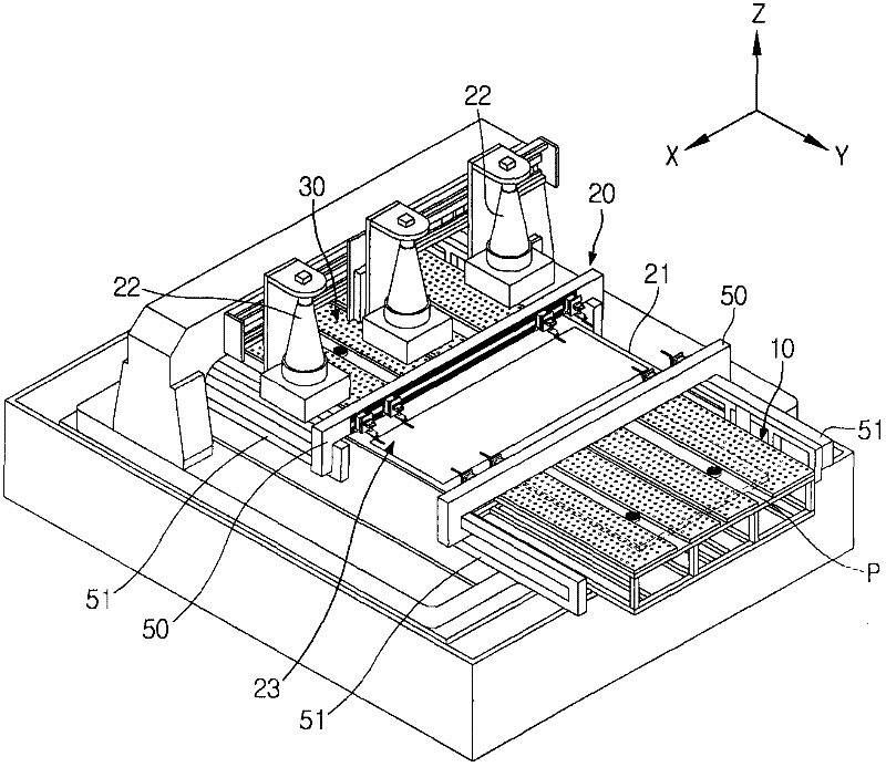
[0021] Such as figure 1 As shown, the array testing device according to the first embodiment of the present invention includes a loading unit 10 for loading a glass panel P on the device, a testing unit 20 for testing the glass panel P loaded by the loading unit 10, and 20 The glass panel P to be tested is unloaded from the unloading unit 30 of the device.

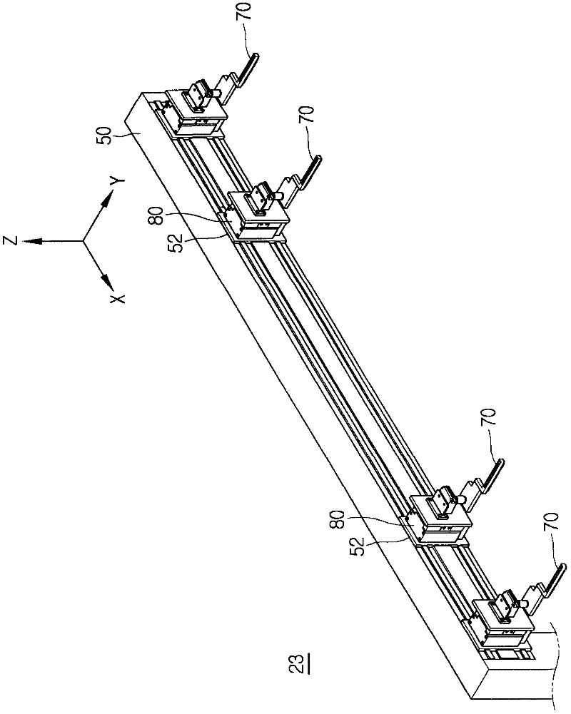
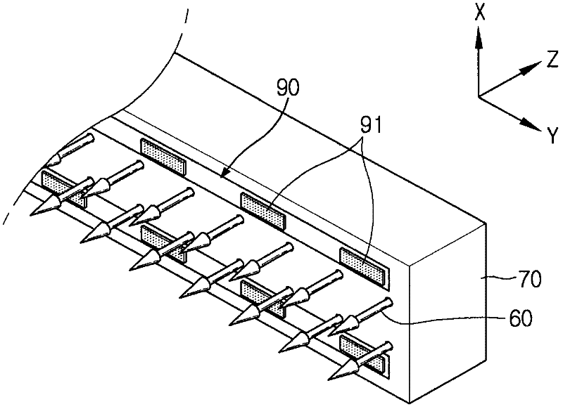
[0022] The testing unit 20 tests the glass panel P for electrical defects. The test unit 20 includes a light-transmitting support plate 21 , a test module 22 , a probe assembly 23 and a control unit (not shown). The glass panel P loaded by the loading unit 10 is placed on the light-transmitting support plate 21 . The testing module 22 tests electrical defects of the glass panel P placed on the light-transmitting support plate 21 . The probe a...


PUM


Abstract

The invention discloses an array testing device. The array testing device is used for removing particles possibly generated when a probe pin is pressed on a corresponding electrode on a glass panel or when an electric signal is applied from the probe pin to the electrode.

Description

technical field [0001] The invention relates to an array testing device for testing glass panels. Background technique [0002] In general, a flat panel display (FPD) is an image display device that is lighter and thinner than a television or monitor having a Braun Tube. Liquid crystal displays (LCDs), plasma display panels (PDPs), field emission displays (FEDs), and organic light emitting diodes (OLEDs) are representative examples of flat panel displays that have been developed and used. [0003] LCDs among these FPDs are image display devices that display desired images in a manner of independently supplying data signals based on image information to liquid crystal cells arranged in a matrix shape, and thereby controlling light transmittance of the liquid crystal cells. LCDs are thin and light, and have many other advantages including low power consumption and low operating voltage, and thus are widely used. A typical manufacturing method of a liquid crystal panel used i...

Claims


Application Information

Patent Timeline
IPC IPC(8): G09G3/00G01R1/073
CPCG01R1/04G01R1/073G01R1/16G01R31/2886G01R31/50
Inventor 朴廷喜
Owner TOP ENG CO LTD
Why Eureka
Try Eureka