
Rail vehicle

A vehicle and vehicle antenna technology, applied in the field of rail vehicles, can solve problems such as instantaneous interference

Inactive Publication Date: 2015-02-25
SIEMENS MOBILITY GMBH
View PDF4 Cites 0 Cited by
  • Summary
  • Abstract
  • Description
  • Claims
  • Application Information

AI Technical Summary

Problems solved by technology

Corresponding momentary disturbances are also caused by the switching on and off of the main switch of electrically driven rail vehicles

Method used


Image

  • Rail vehicle

Examples


Embodiment Construction

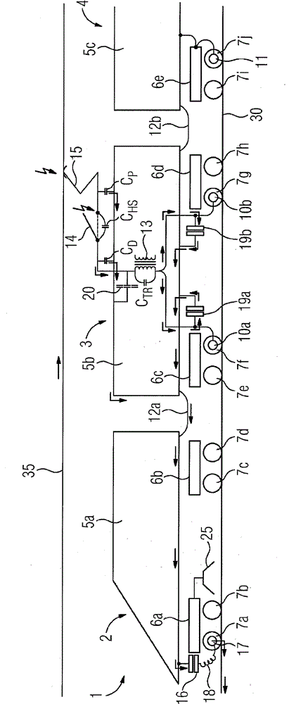
[0031] In the figures, a rail vehicle 1 in the form of an electric multiple unit is shown. Here, only half of the train is depicted for reasons of clarity. The rail vehicle 1 has an end car 2 , a transformer car 3 and a center car 4 which is only partially shown. Cars 2, 3, 4 respectively have carriages 5a, 5b, 5c and bogies 6a, 6b, 6c, 6d, 6e.

[0032] It should be emphasized that the description of the drawings is only an extremely simplified schematic diagram for the purpose of clarifying the invention. Furthermore, it should be pointed out that the cars 5 a , 5 b , 5 c of the cars 2 , 3 , 4 of the rail vehicle 1 are denoted in their entirety as cars below. On the one hand this applies in the context that the invention described according to the embodiments can also be used in rail vehicles with continuous carriages; moreover, the carriages 5a, 5b of the cars 2, 3, 4 in the embodiment of the drawings , 5c are electrically connected to each other via potential compensati...


PUM


Abstract

A rail vehicle has at least one vehicle antenna of a train safety system directed toward the track. To increase resistance to interference, the rail vehicle is configured such that the body of the rail vehicle and an axle arranged in the region of an end of the rail vehicle are electrically connected by way of a capacitive connection and the at least one vehicle antenna is arranged at a greater distance from the end of the rail vehicle than the axle that is electrically connected to the body.

Description

technical field [0001] The invention relates to a rail vehicle having at least one vehicle antenna of a train safety system pointing towards the rail. Background technique [0002] Rail vehicles of this type are generally known, wherein the vehicle antenna of the corresponding rail vehicle is usually used to transmit data between a device arranged on the track side, for example in the form of a transponder, in the track and the rail vehicle. Depending on the type of the respective train safety system or train intervention system and the respective section-side device, different types of vehicle antennas can be used here. [0003] Vehicle antennas pointing towards the track, ie essentially pointing downwards, can have the problem, in particular depending on the type of rail vehicle in question, that they can be affected by electrical interference. Therefore, in such a rail vehicle, which extracts the energy required for its forward movement from overhead wires or conductor r...

Claims


Application Information

Patent Timeline
Patent Type & Authority Patents(China)
IPC IPC(8): B61L3/12
CPCB61L3/12B61L2027/0044B61L2027/202
Inventor 吉多·沃尔夫曼弗雷德·德特贝克
Owner SIEMENS MOBILITY GMBH
Learn More