Three dimensional video display device

一种三维视频、显示装置的技术,应用在显示装置、辨认装置、光学等方向,能够解决不能显示等问题

Inactive Publication Date: 2012-07-11
SHARP KK
View PDF10 Cites 18 Cited by
  • Summary
  • Abstract
  • Description
  • Claims
  • Application Information

AI Technical Summary

Problems solved by technology

However, either method is used on a flat-panel display, so display on a curved surface cannot be performed.

Method used


Image

  • Three dimensional video display device
  • Three dimensional video display device
  • Three dimensional video display device

Examples


no. 1 approach

[0042] (Outline of 3D Video Display Device 1 )

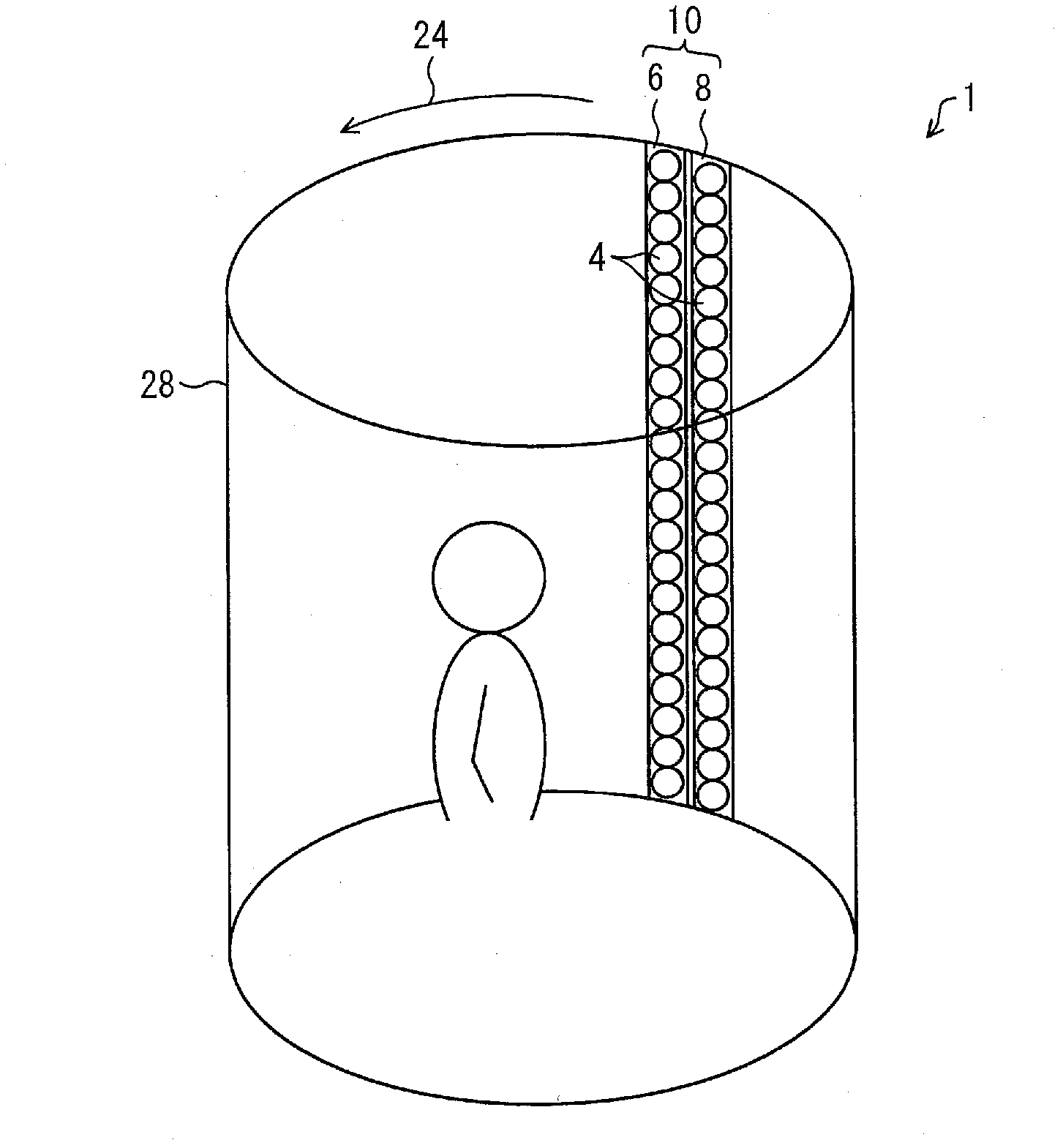
[0043] refer to figure 1 The outline of the 3D video display device 1 of this embodiment will be described. figure 1 It is a diagram showing the configuration of the three-dimensional video display device 1 of the present embodiment.

[0044] Such as figure 1 As shown, the three-dimensional video display device 1 of the present embodiment includes an LED unit 10 (display unit 10) including an LED array 6 for a left eye (video display unit for a left eye) and an LED array 8 for a right eye (a video display unit for a right eye). unit), and the display unit 28. The display unit 28 has a cylindrical shape and is arranged around a predetermined central axis not shown in the figure. Moreover, the display part 28 has the rotation mechanism which rotates the LED unit 10 in the circumferential direction (direction shown by the arrow 24) centering on the said central axis along the upper and lower edge parts.

[0045] The LED unit 1...


PUM


Abstract

In a three dimensional video display device (1), an LED unit (10) rotates along the upper and lower edges of a display unit (28) in the direction of arrow (24). The LED unit (10) has a left-eye LED array (6) and a right-eye LED array (8), both having a plurality of LEDs (4) lined up vertically thereon. The left-eye LED array (6) displays an image for the left eye by using an afterimage effect, generated by rotating while displaying lines of pixel groups which form the left-eye image. The right-eye LED array (8) displays an image for the right eye by using an afterimage effect, generated by rotating while displaying lines of pixel groups which form the right-eye image. The light from the left-eye image enters the left eye of a viewer, and the light from the right-eye image enters the right eye of the viewer. The viewer perceives a three dimensional video in a range of 360 DEG on the basis of binocular parallax.

Description

technical field [0001] The present invention relates to a three-dimensional video (image) display device, and particularly relates to a three-dimensional video display device utilizing the afterimage (persistence of vision) effect produced by rotating a light-emitting element. Background technique [0002] In recent years, due to the rapid development of video display technology, development of technology for displaying three-dimensional video in addition to technology for displaying two-dimensional video is being advanced. The display technology of 3D video can be used in entertainment, medical scene, or electronic catalog, advertisement, etc., and its scope of application is very wide. [0003] As a three-dimensional video display technology, there is a polarization glasses method. In this method, the video for the left eye and the video for the right eye are arranged on each dot row of the display screen, and a linear polarizing filter is provided on the front side there...

Claims


Application Information

Patent Timeline
Patent Type & Authority Applications(China)
IPC IPC(8): G02B27/22G09F9/00G09F9/30G09F9/37G09F19/12H04N13/04G02B30/25G02B30/27G02B30/30
CPCG02B27/2214G09F2013/189H04N13/0459G02B27/26H04N13/0434G09F9/33G09F19/12G09F9/37H04N13/0438H04N13/337H04N13/341H04N13/363G02B30/25G02B30/27G02B30/30G09F19/125
Inventor 吉田秀史前田强柴田谕
Owner SHARP KK
Why Eureka
Try Eureka