Novel mechanical sealing performance testing apparatus

A technology of mechanical seal and test device, which is applied in the direction of using liquid/vacuum degree for liquid tightness measurement, by measuring the acceleration and deceleration rate of fluid, etc., which can solve the problem of unbalanced axial force and increase the connection structure between the power input shaft and the power device. The complexity and the inability of the measured sealing surface to adjust the proportional pressure, etc., can reduce the influence of the inaccurate measurement of torque and leakage.

Inactive Publication Date: 2012-07-18
滁州扬安高科技术有限公司
View PDF5 Cites 24 Cited by
  • Summary
  • Abstract
  • Description
  • Claims
  • Application Information

AI Technical Summary

Problems solved by technology

For the single cantilever shaft mechanical seal test device, the power input shaft penetrates into one end cover of the seal cavity, such as figure 1 As shown, the measured mechanical seal is used as the seal of the chamber, which is similar to the scene, but the seal shaft end is in the seal chamber, and the shaft end is subjected to the action of medium pressure to generate axial force, and the medium acting area on both sides of the seal is not equal. , will also generate axial force, and the bearing resistance torque caused by different axial forces is different, which affects the measurement accuracy of end face friction torque; for the double cantilever mechanical seal test device, such as figure 2 As shown, the axial force caused by the medium pressure on a single shaft end and the axial force caused by the unequal medium action area on both sides of the seal will be balanced by its symmetrical struc

Method used


Image

  • Novel mechanical sealing performance testing apparatus
  • Novel mechanical sealing performance testing apparatus
  • Novel mechanical sealing performance testing apparatus

Examples


Embodiment Construction

[0020] In order to further understand the content, characteristics and effects of the present invention, the following embodiments are given as examples, and detailed descriptions are as follows with accompanying drawings:

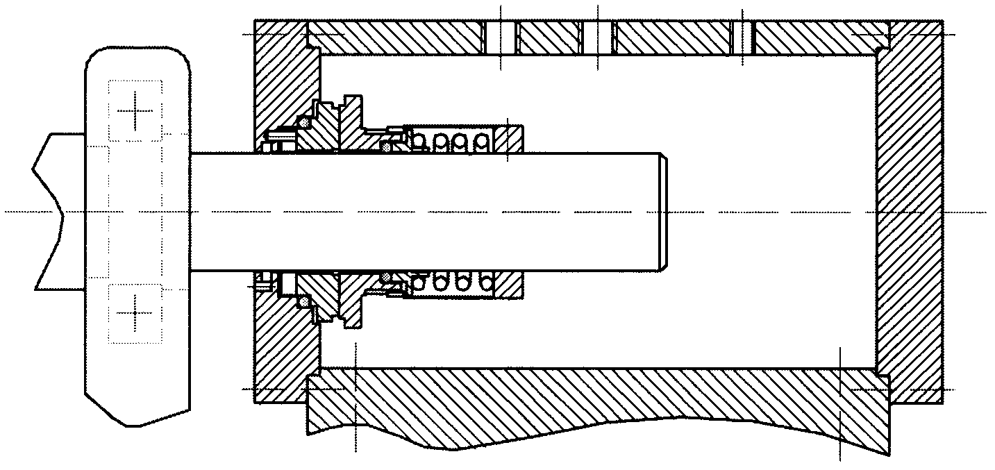
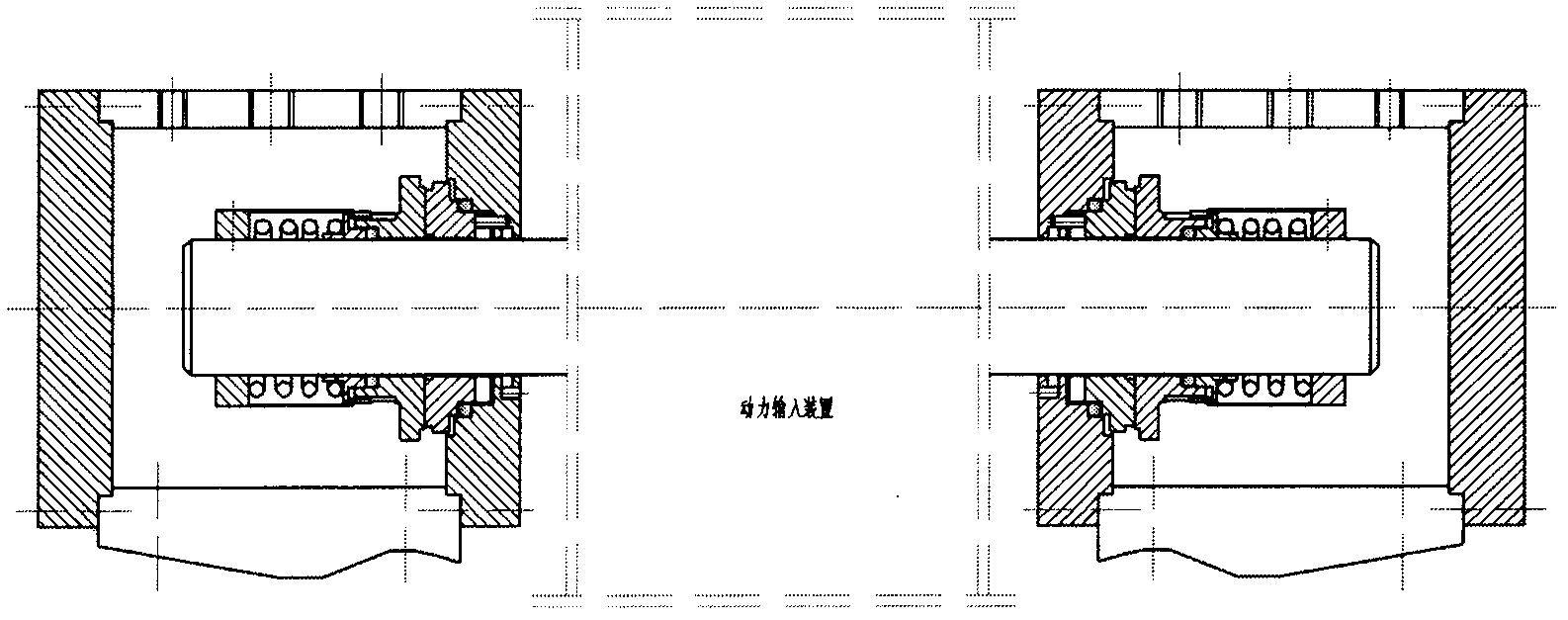
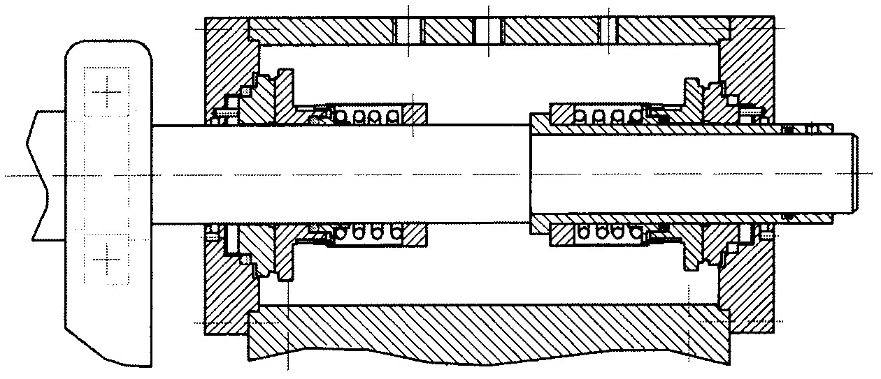
[0021] When installing two pairs of tested seal rings, first install the static ring 7 into the left end cover 6, and at the same time insert one end of the pin 5 into the hole of the left end cover 6, and the other end is stuck in the groove on the end surface of the static ring 7 to prevent the two Relative rotation (e.g. Figure 4 (Shown), then put the left end cover 6 and the static ring 7 in it on the main shaft 4 together, move the carriage 20 to drive the sealed chamber housing 19 to the left to lock it, and lock the left end cover 6 with the sealed chamber housing 19 Fix with screws; the assembly sequence of the remaining parts on the main shaft 4 is: moving ring 8, compression spring seat 9, compression spring 10, moving ring seat 11, pin shaft II21 (...


PUM


Abstract

The invention discloses a novel mechanical sealing performance testing apparatus which is characterized in that a main shaft penetrates through a left end cover and a right end cover on a sealing cavity shell; two pairs of measured sealing rings with the same size are arranged on main shafts at the left end and the right end in the sealing cavity shell; no additional axial force generates at any test medium pressure; two sections of threads of which screw pitches are same and the spiral line directions are opposite are machined on a long shaft sleeve which is in clearance fit with the main shaft; the long shaft sleeve is clockwise rotated to drive a left nut and a right nut which are screwed with the long shaft sleeve to equidistantly move leftwards and rightwards; and a left pressure spring and a right pressure ring are pushed to respectively press two moving rings, so that specific pressures borne by a left pair of sealing surfaces and a right pair of sealing surfaces are identical. The two pairs of sealing rings with the same size are adopted for testing; an average value of test results of the sealing rings is used as a test torque and leakage rate of mechanical sealing of the model number, and thus the influence on the accuracy of the torque and the leakage rate caused by accidental factors such as mounting when only one pair of sealing rings are used for testing is reduced.

Description

1. Technical Field [0001] The invention belongs to the technical field of mechanical seal testing, and particularly relates to a novel mechanical seal performance test device with no additional axial force and two seal end faces with equal specific pressure adjustment. 2. Technical background [0002] As the shaft seal of the power input shaft of pumps, compressors and agitators, mechanical seals are widely used in petrochemical, electric power, aviation and other fields. With the continuous progress of material science and manufacturing technology, the life and reliability of mechanical seals have been greatly improved, but in industrial applications, their failures are still common. In order to obtain a mechanical seal with long life and stable performance, it is not only necessary to further optimize and design the mechanical seal structure on the basis of previous studies, but also to develop a reliable and convenient mechanical seal performance test device. [0003] According...

Claims


Application Information

Patent Timeline
IPC IPC(8): G01M3/26
Inventor 涂桥安孙见君陶丹萍胡琼陶凯
Owner 滁州扬安高科技术有限公司
Why Eureka
Try Eureka