Movable clamping plate structure

A mobile and clamping technology, which is applied in aircraft assembly, aircraft parts, ground installations, etc., can solve the problems of large workshop space occupied by storage, high cost of pallets, and potential safety hazards in lifting, so as to achieve economical manufacturing and universal applicability Effect

Inactive Publication Date: 2012-07-25
XIAN AIRCRAFT IND GROUP
View PDF0 Cites 2 Cited by
  • Summary
  • Abstract
  • Description
  • Claims
  • Application Information

AI Technical Summary

Problems solved by technology

In the prior art, pallets are usually installed at each station, and working elements (positioners, compactors, etc.) are set on the pallets. The pallets need to be lifted, and sometimes it is necessary to design and manufacture pallet racks. The pallets of this structure The board is inconvenient to use, there is a safety hazard in lifting, and the storage takes up a lot of space in the factory building, so the cost of the pallet with this structure is relatively high

Method used


Image

  • Movable clamping plate structure
  • Movable clamping plate structure
  • Movable clamping plate structure

Examples


Embodiment Construction

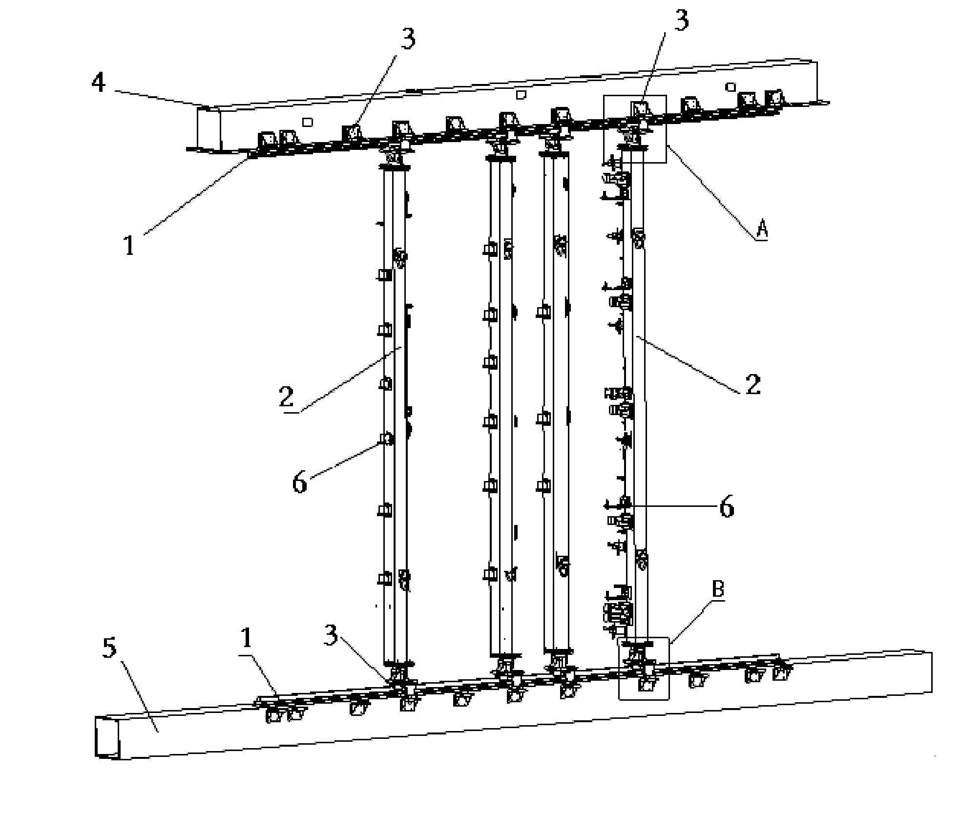
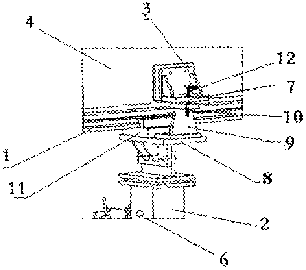
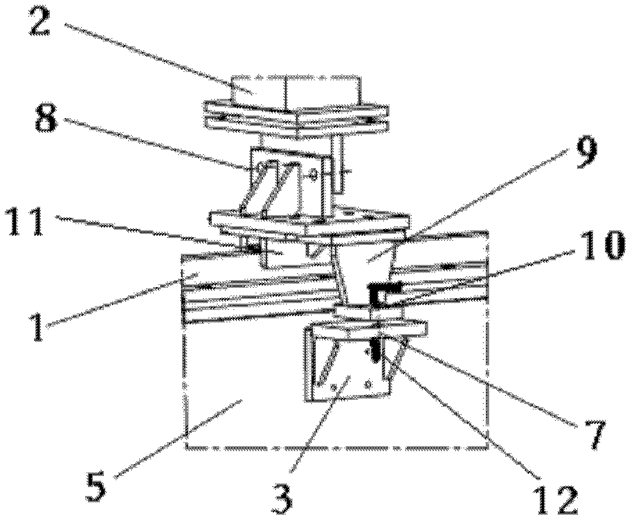
[0013] Referring to the accompanying drawings, a pallet structure that moves along the track, the mounting base of the pallet structure includes a set of corresponding upper beams 4 and lower beams 5 on a longitudinal three-dimensional surface, and the upper beam 4 and the lower beam 5 The relative inner side is respectively provided with rails 1, and the clamp body 2 is a steel or wooden columnar body. , used to install various tooling positioning fixtures; both ends of the clamp body 2 are fixed with the slider 11 through the connector 8, and the slider 11 is embedded on the slide rail 1, so that the clamp body 2 can be easily realized on the slide through the slider. Sliding on the rail 1; in order to facilitate the work at different stations, a positioning structure is provided between the clamp body and the slide rail, and the positioning structure is composed of the station feet 3, the positioning plate 9 and the positioning pin 12, The positioning structure between the ...


PUM


Abstract

The invention discloses a movable clamping plate structure. Vertically-parallel slide rails are fixed on an upper beam and a lower beam respectively; the two ends of a clamping plate body are fixed together with a slider inlaid on a track through a connecting piece respectively; the clamping plate body is an upright-shaped rigid structure; and multiple connection holes are arranged on the upright of the clamping plate body. The movable clamping plate structure disclosed by the invention has the advantages that the clamping plate can move between the upper and lower beams to meet the requirements on the clamping plate body between adjacent stations and overcome the problems in dismantling or hoisting the clamping plate; and the movable clamping plate structure has universal applicability to an airplane fixture design.

Description

technical field [0001] The application relates to the design and manufacture of a tooling frame clamp in aircraft production, in particular to a movable clamp structure. Background technique [0002] In the process of designing and manufacturing pallets on assembly tooling racks of aircraft products, we often encounter the design and manufacture of pallets with multiple stations and large sizes, each station has the same or similar shape, and each station has the same or similar components. . In the prior art, clamps are usually installed at each station, and working elements (positioners, compactors, etc.) are set on the clamps. The clamps need to be lifted, and sometimes it is necessary to design and manufacture a pallet placement frame. The clamps of this structure The board is inconvenient to use, there is a safety hazard in lifting, and the storage takes up a lot of space in the factory building, so the cost of the pallet with this structure is relatively high. Conte...

Claims


Application Information

Patent Timeline
Patent Type & Authority Applications(China)
IPC IPC(8): B64F5/00B64F5/10
Inventor 惠增胜蒋馨郝巨张晨阳赵平
Owner XIAN AIRCRAFT IND GROUP
Why Eureka
Try Eureka