Air sac pushing device for motor vehicle collision test

A vehicle collision and propulsion device technology, applied in the field of rail vehicles, can solve the problems of short gas impact time, high manufacturing difficulty, long construction period, etc., and achieve the effects of low cost, simple production, high energy and speed

Inactive Publication Date: 2012-07-25
SOUTHWEST JIAOTONG UNIV
View PDF5 Cites 18 Cited by
  • Summary
  • Abstract
  • Description
  • Claims
  • Application Information

AI Technical Summary

Problems solved by technology

In order to study and explore the collision characteristics of rolling stock at different speeds, there are currently two approaches for the study of collision phenomena: one is to use large-scale software to calculate some collision characteristics by establishing simulation models of rolling stock under different parameter states. phenomenon, this method is simple and does not require a large amount of investment, but there are still some differences in the collision problems that occur under actual working conditions; the second is to establish a corresponding experimental platform for actual collision verification, this method is true, and it can be concluded that The data are reliable and play an irreplaceable role in in-depth research on the collision of rolling stock. However, the investment is large and the construction period is long. Especially under experimental conditions, large-scale propulsion equipment must be used to obtain the equivalent collision speed of rolling stock. At present, large-scale pistons are routinely used. Cylinder propulsion system, this system has certain problems or difficulties in design, installation, operation and maintenance, etc.; in addition, a gas launch propulsion system similar to missiles can be used to make the locomotive and vehicle accelerate by gas in a channel, but also There are problems such as short gas impact time, high manufacturing difficulty, sonic boom, etc.

Method used


Image

  • Air sac pushing device for motor vehicle collision test
  • Air sac pushing device for motor vehicle collision test
  • Air sac pushing device for motor vehicle collision test

Examples


Embodiment Construction

[0016] In order to better understand the technical solution of the present invention, the present invention will be further described below in conjunction with the accompanying drawings and embodiments.

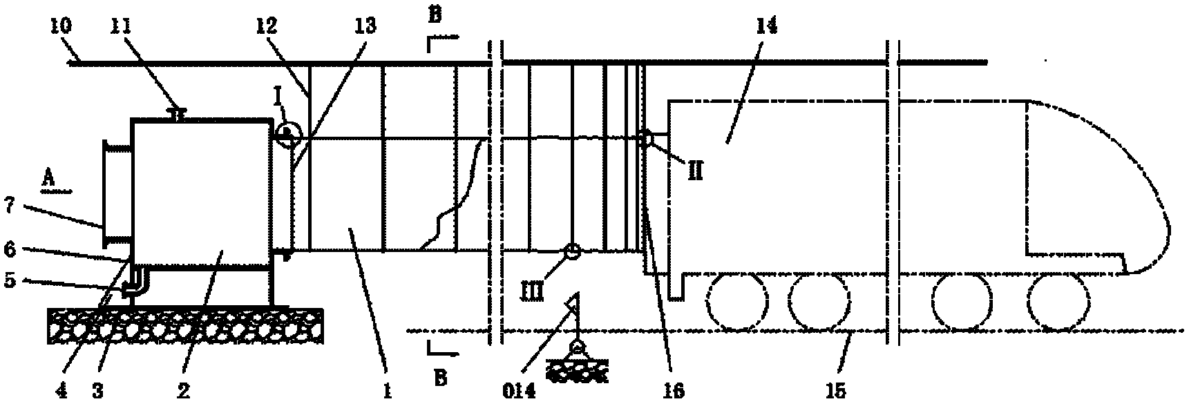
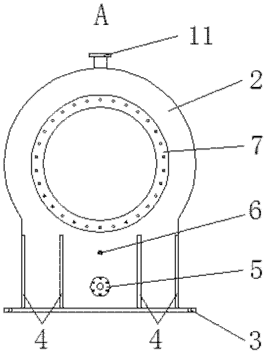
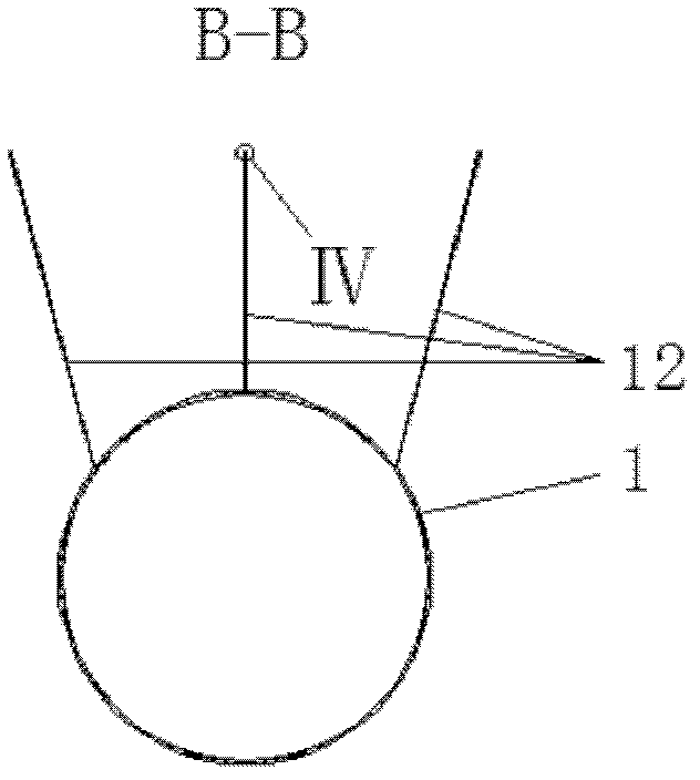
[0017] An embodiment of the present invention provides an airbag propulsion device for a locomotive vehicle collision test, such as figure 1 , figure 2 , image 3 , Figure 4 , Figure 5 , Image 6 , Figure 7 As shown, the device includes: a fixed inflatable cylinder body 2 and a collapsible cylindrical flexible air bag 1. The inflatable cylinder body 2 is provided with a mounting seat 3 , an air inlet 7 , an exhaust port 11 , a water discharge port 5 , an air gauge interface 6 and an air bag interface 13 . The mounting seat 3 set on the fixed inflatable cylinder body 2 is connected with the foundation, the air inlet 7 is connected with the air supply system, the exhaust port 11 is connected with the exhaust valve, the drain port 5 is connected with the drain valve; t...


PUM


Abstract

The invention discloses an air sac pushing device for a motor vehicle collision test, which mainly consists of a fixed inflating cylinder and a foldable cylindrical flexible air sac. The foldable cylindrical flexible air sac is connected with the inflating cylinder via a gland and a sealing device; more than two cylindrical cloth sacs are sewn and reinforced to form the foldable cylindrical flexible air sac, an air opening is arranged at one end of the foldable cylindrical flexible air sac and connected with an air channel of the inflating cylinder, a back cover at the other end of the foldable cylindrical flexible air sac is reinforced by more than two layers of cloth, and the total foldable cylindrical flexible air sac is hung on a spatial hanger. Continuous long-term long-stroke acting of a movable piston is realized, so that an active vehicle (a colliding vehicle) runs at the highest running speed. The air sac pushing device has the advantages that experiment cost is low, acting force is large and lasting, and acceleration of the active vehicle is obvious. In addition, the air sac pushing device can be used for pushing tests of heavy motor vehicles.

Description

technical field [0001] The invention relates to the technical field of rail vehicles, in particular to a collision test device for realizing high-speed propulsion of rolling stock. Background technique [0002] Rolling stock collision accident is one of the most serious accidents in rolling stock operation. In order to study and explore the collision characteristics of rolling stock at different speeds, there are currently two approaches for the study of collision phenomena: one is to use large-scale software to calculate some collision characteristics by establishing simulation models of rolling stock under different parameter states. phenomenon, this method is simple and does not require a large amount of investment, but there are still some differences in the collision problems that occur under actual working conditions; the second is to establish a corresponding experimental platform for actual collision verification, this method is true, and it can be concluded that Th...

Claims


Application Information

Patent Timeline
Patent Type & Authority Applications(China)
IPC IPC(8): G01M17/08G01M7/08
Inventor 肖守讷张卫华柳忠彬阳光武
Owner SOUTHWEST JIAOTONG UNIV
Why Eureka
Try Eureka