Plasma jet-stream protective cover

A technology of plasma and protective cover, which is applied in the direction of metal material coating process, fusion spraying, coating, etc., can solve the problems of complex structure, increased equipment operation cost, and ineffective oxidation and nitriding effect, so as to avoid oxidation and Nitriding, the effect of reasonable structure

Inactive Publication Date: 2012-08-01
WUHU YINGRI TECH CO LTD
View PDF9 Cites 9 Cited by
  • Summary
  • Abstract
  • Description
  • Claims
  • Application Information

AI Technical Summary

Problems solved by technology

However, the protection device must be connected to the spray gun and extend outward, and the length of the protection tube must be long enough, otherwise the effect of preventing oxidation and nitriding is not obvious
Chinese document CN102361529A is a plasma jet protective cover that adopts coaxial protective air flow, which is a cylindrical jet protective cover. It adopts fixed protection to block the flow of ambient air to the jet. In addition, an additional section is used to adjust the length of the protective cover. The scheme disclosed by CN102361529A is the same as that of CN200920097328. Compared with the 4 scheme, although it has been improved, the mechanically isolated protective tube or additional section is also used, and the structure is complicated
[0004] Existing vacuum plasma spraying equipment, such as document CN101126144, carries out spraying in airtight vacuum chamber, and purpose is to prevent metal spraying oxidation, by controlling the vacuum degree of vacuum chamber, filling inert gas or filling active gas, yet due to the increase of vacuum The chamber is limited by the size of the vacuum chamber, which greatly increases the operating cost of the equipment, and at the same time limits the size of the sprayed workpiece

Method used


Image

  • Plasma jet-stream protective cover
  • Plasma jet-stream protective cover
  • Plasma jet-stream protective cover

Examples


Embodiment

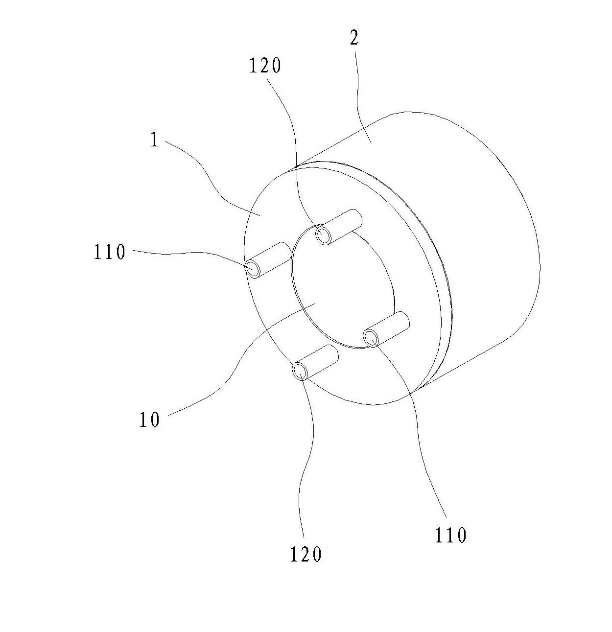
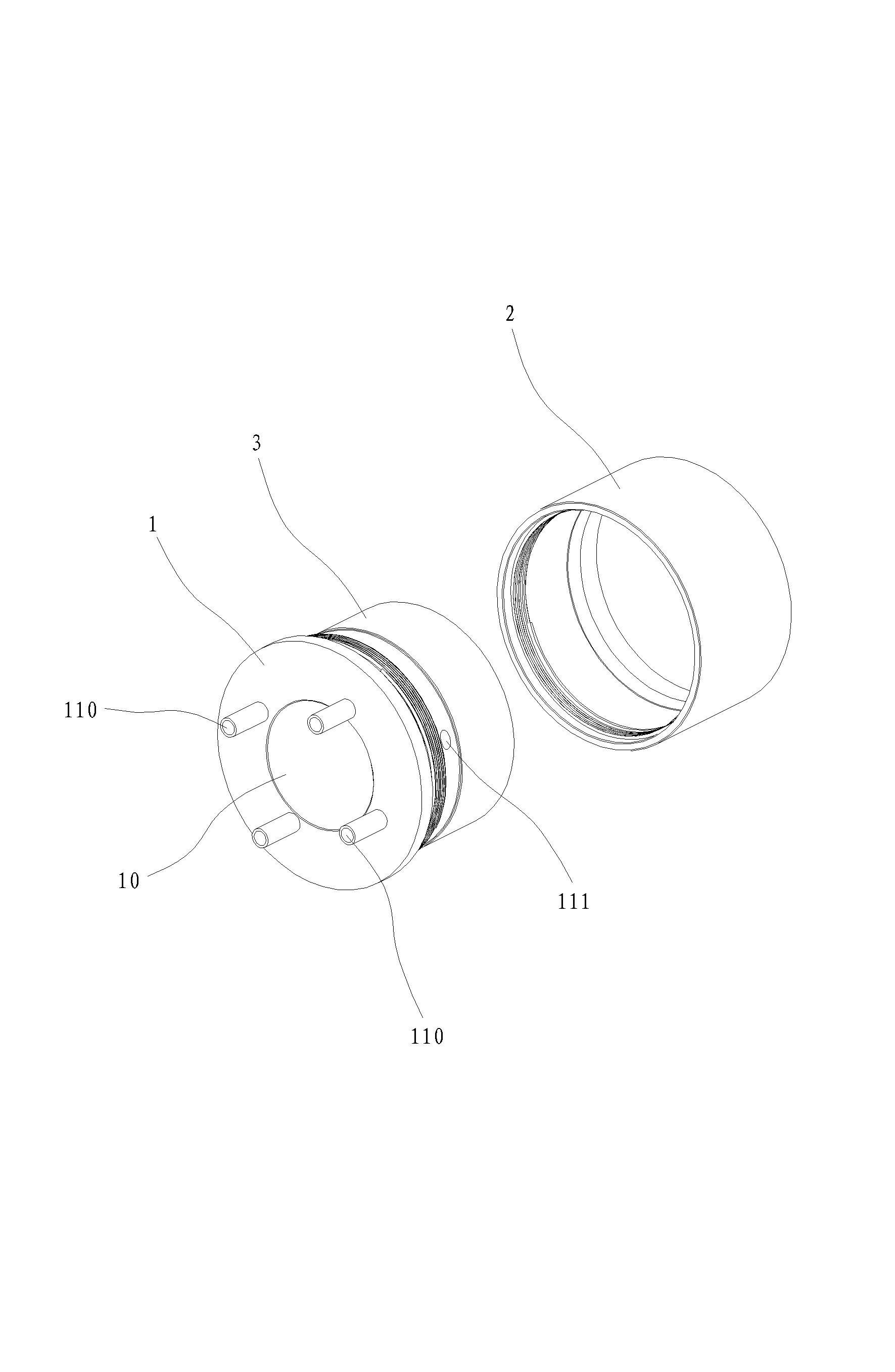
[0028] Example: see Figure 1 to Figure 5 , a plasma jet shield, comprising a jet core 1, an outer ring 2 and an inner ring 3, wherein:

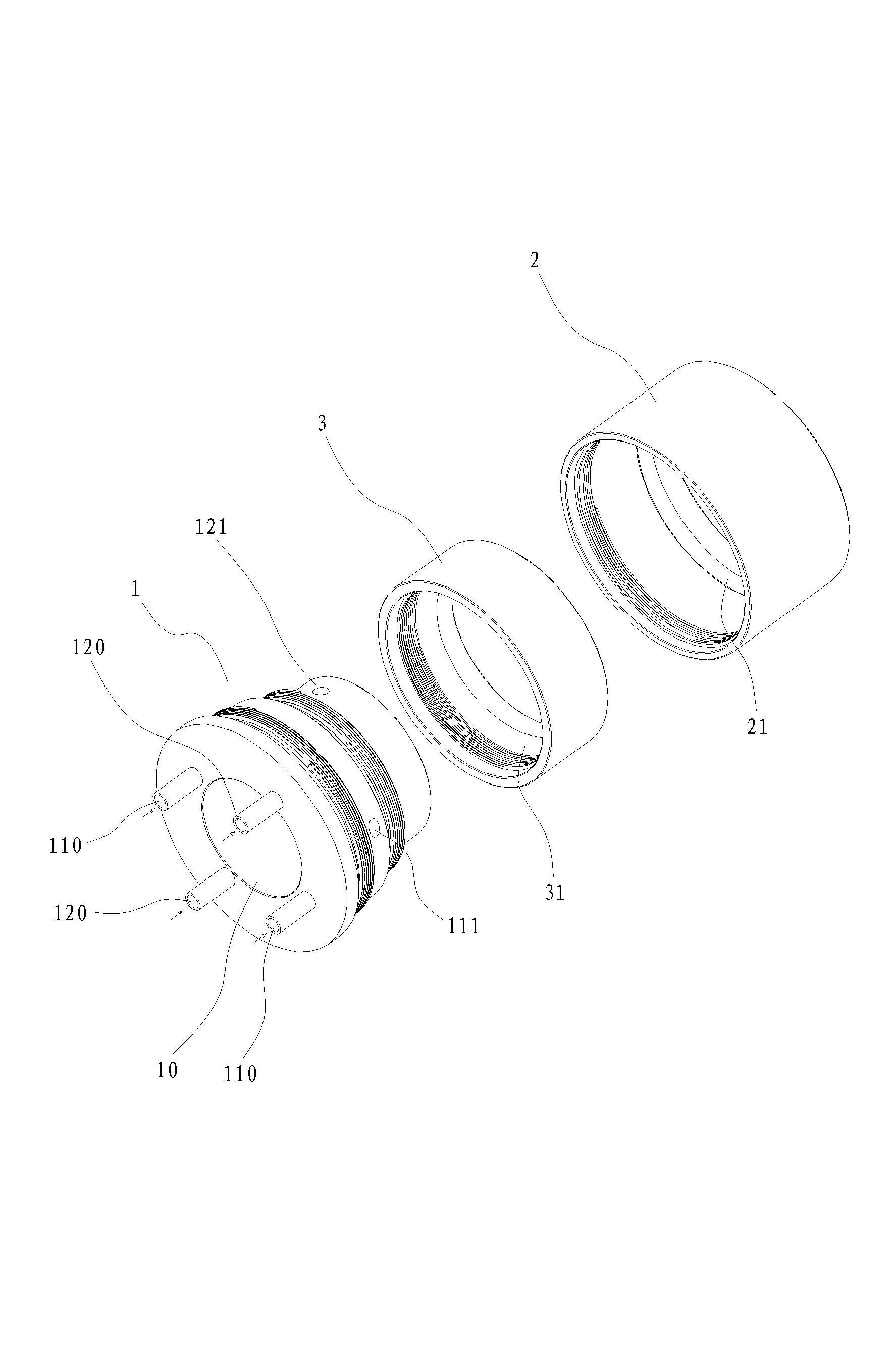
[0029] The jet core 1 has a central axial through hole 10, and one end surface of the core is provided with two groups of air inlet holes 110, 120. Two groups of air outlet holes 111, 121, each group of air outlet holes are symmetrically distributed, and the two groups of air outlet holes communicate with the matching air inlet holes to form inner and outer layers of protective gas 11, 12;

[0030] The inner ring 3 is connected to the jet core 1 and cooperates with a group of air outlet holes at the front end of the peripheral wall of the core. The inner peripheral wall of the inner ring and the front end of the peripheral wall of the jet core form an annular flow channel to form an inner protective gas channel;

[0031] The outer ring 2 is connected to the jet core 1 and cooperates with another group of air outlet holes on the peripheral w...


PUM


Abstract

The invention discloses a plasma jet-stream protective cover, which comprises a jet-stream core body and a jet-stream core body center axial direction through hole. One end face of the core body is provided with two groups of air intakes. A core body perisporium is correspondingly provided with two groups of air outtakes. The two groups of air outtakes are communicated with the corresponding air intakes so as to form an inner layer of protection air and an outer layer of protection air. An inner ring is connected to the jet-stream core body and is cooperated with one group of air outtakes on the front end of the core body perisporium. An outer ring is connected to the jet-stream core body and is cooperated with the other group of air outtakes of the core body perisporium. The jet-stream core body, the inner ring and the outer ring are together assembled into a cover structure. One end of the cover structure is used for air suction, and the other end forms two layers of protection air rings and is extended forward so as to enable the plasma jet-stream to be effectively separated from the atmosphere. One protective device is installed on one spray gun of an atmosphere plasma spray coating device, completely-molten or half-molten powder is protected inside the protective air along with the flame through the protection of the air so as to be separated from the atmosphere, the oxidization and nitrogenization of the powder in a high temperature can be reduced, and the quality of a target coating can be improved.

Description

technical field [0001] The invention discloses a plasma jet protective cover, which belongs to the technical field of plasma thermal spraying manufacturing according to the International Patent Classification (IPC). Background technique [0002] Plasma spraying technology uses plasma as a heat source to heat ceramics, alloys, metals and other materials to a molten or semi-molten state, and sprays them on the surface of the pretreated workpiece at high speed to form a firmly attached surface working layer. Spraying improves the density and bonding strength of the coating. Chinese patent documents CN1688735, CN1775994, CN101168830, etc. disclose the current high-energy plasma spraying equipment. However, in the existing plasma spraying method under normal pressure air environment, the material is sprayed in a molten or semi-molten state. Due to contact with the atmosphere, air is easily involved in the jet, and phenomena such as oxidation and nitriding occur, especially in hig...

Claims


Application Information

Patent Timeline
Patent Type & Authority Applications(China)
IPC IPC(8): C23C4/12C23C4/134
Inventor 罗永春
Owner WUHU YINGRI TECH CO LTD
Why Eureka
Try Eureka